CP Executive train in Albany

CP Executive train in Albany

Monday, February 20, 2017

Assembling the Legs

A quick sketch was made to determine exactly how I should assemble the legs together, and then I compared it to the leg fixture I had glued up. They didn't match. Originally I was going to have my legs spaced about 20" apart with the L-girders on the inside of them. I changed my mind and moved the legs closer together so that the L-girders would be outside. Recessing the legs in a bit more (though admittedly not by much) may prevent accidental bumps to the layout. So, I modified my jig and began assembling things.

One of the main considerations I had when deciding on layout height was my wife's concern that if it were too high, she wouldn't be able to see it easily. I like my layouts high (48"-60") where as she prefers them lower, like what you would see at an N-trak exhibit (40"). However, when we were at the Springfield show recently Model Railroad Hobbyist e-magazine had a really nice booth set up, and featured in it was an HO scale switching layout. Not only did the modeling portion look great, but the physical construction details (layout height, fascia color and material, recessed toggle switches) made it look professional and clean. And, my wife liked the height. So much that we asked how tall it was and Joe Fugate (publisher of MRH) pulled out a tape measure and checked for us. 50". So, that became the height for my new layout.

L-girder has a lot going for it but one problem is that it is really thick. The girders that are 3-5" tall, the cross joists on top are usually another 3-4" thick, and then you have risers, the track support plywood, cork roadbed, and actual track. It adds up and could be as much as 7-8" more above the girders.

My box-frame layout sections will be about 3.5" thick, with another half-inch of plywood on top, for a total of 4." I needed the L-girders to be about 44" tall so that when I added any cross supports, my open grid sections, and the leveling bolts on the bottom of the legs my layout would come up to about 50" tall. Which meant my legs needed to get shortened by about 4". No problem, I borrowed my uncle's chop saw which made nice clean ends perfect for accepting the 5/16" tee nuts that are necessary for the bolts for leveling the legs.

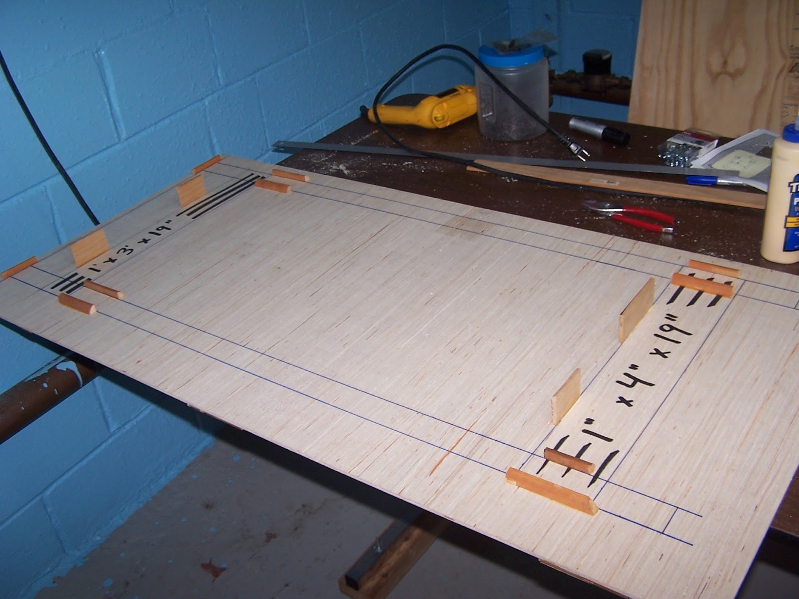
Finally, each pair of legs was secured to some 1x3" and 1x4" stock that I cut to length and it all was glued and screwed together. I originally planned to go with diagonal cross braces but I have seen many people use perpendicular ones and they are much easier to cut if you have a chop saw. Also, some people specifically advocate not gluing anything else besides the L-girders together and instead just relying on the screws to hold it all in place. Because I wanted my leg assemblies to be rock solid, I glued and screwed it all together. Overkill? Perhaps, but one think I knew I would need to contend with was a the occasional bump from the dog (or me)!

Tuesday, February 7, 2017

Starting the L-girder benchwork

I have been struggling with how to support my layout sections. I originally wanted shelf brackets but am not going to drill holes in my basement wall at this time. Then I thought about cheap plastic banquet tables, which are sturdy and would work well. But, the downside is that they are too short in height and the cost and effort to make them taller isn't worth it. Plus, under the layout access could be difficult to do wiring or anything, and any connections between them like clamps would need to overhang the table ends to work. I looked into plastic shelving units to support them and while the added storage would be awesome I would need a lot of shelves, and they would all need to be shimmed accordingly for my uneven floor.

I guess I could just mount legs on the bottom of my layout sections but I really want the ability to flip them over or on their side to work on them, and legs will make that difficult even if I have removable legs. Plus, I would need to build a lot of legs. Perhaps I am overthinking this and legs might just work out fine. But, I want to move forward and so I came to...

L-Girder benchwork!
I originally threw it out as old-fashioned and unworkable. Designed by Linn Westcott (the diagram at right is taken from his benchwork book), one of its strengths is that it doesn't require precise lumber cuts. That means no chop saw is required. While I overlooked this benchwork system originally because it isn't easy to make strong sections required for LDEs, here I can build a simple L-girder framework to go below my LDEs. And, I won't need a million legs to support it and I can make them as tall as I want.

So, with this idea fresh in my head I ran off to the lumber store to purchase some supplies to make a fixture to help build the leg assemblies square and identical. I also went looking for some 2" x 2" lumber for the legs but instead what I found was a pile of warped, twisted, wood. So, I instead I bought 16 pieces of 1" x 2" pine boards. They were very straight, all were about the same length (4'), and as a bonus I wouldn't need to cut them to size as I wanted the layout L-girders to be about 4' off the ground. I glued and screw them back to back and now have very straight 2x2 lumber for my legs. They will cost more than a regular 2x2 stock but in total each one will cost me less than $5. I only need 12 legs, so it was a good deal. If I had a table saw and could rip down 2x4 lumber, it would be a different story.

If you look at my drawing at the right, you can spot to omissions pretty quickly. First, the L-girders look pretty empty and not really suitable to hold the layout sections. But, I will secure some 1x2" lumber laid flat along the way, bridging the two girders. They are yellow in the diagram, and I omitted them from most of the benchwork for clarity. Second, I don't know how I am going to handle the section where I plan to enter/exit the interior of the layout.

Then, I pre-drilled seven or eight holes along one of the 2x2 pieces, spread glue on the back, put it on top of another piece and carefully lined up one end. Some #6 drywall screws, 1+1/8" long, went into the soft pine perfectly and things were set. I had to check the alignment of the legs before setting each screw but these pieces will be perfect for what I need once the glue sets. I don't know if predrilling was necessary but I did the top piece. I used a #6 countersink drill bit that I bought on Ebay for a buck or so. It took a month to arrive from China but it worked great. Switching bits between that and the screw driver bit was very annoying though.

Next, I made my L-girders. The "back" side (the side opposite the one facing the stairway where I plan to enter) will have a pair of 12' long L-girders. The two sides will each have a pair of 10' L-girders attached, making a "C" shape. The front, or entrance, is unknown yet. I might build a shorter L-girder to fit between the two sides, or I might try and make a lift section combined with a smaller piece. I will cross that bridge later.

Anyway, finding 10' and 12' long 1x3 lumber was impossible at Home Depot and Lowes. Even 1x4, slightly oversize for my needs but extra strong, wasn't available. But, an 84 Lumber about 20 minutes away had 1x4s in lengths up to 14', so a quick Saturday morning trip found two 12' and four 10' long pieces sticking out the back of my Toyota Corolla. They only have "select" grade which was knot and warp free but at a slightly more expensive price than HD/L. To me, it was worth it.

Then, for the top of the L-girder I went to Lowes and picked out a bunch of 8' long 1x2 stock that was straight and knot free. I will need to splice them to get the proper length, but at least the 1x4s aren't spliced. A lot of pre-drilling and gluing later (I bought a gallon of wood glue for the whole project, and it should last me years), I had my L-girders and legs ready for the next step.

A new member to our household is "Clover," our recently adopted 5 year old golden retriever. She was serving as my apprentice as I worked on the benchwork. Some of the sawdust landed on her, making a mess of sorts. And, she has a fondness of chewing wood scraps I left lying around on the floor. I can't do that again!

Total cost so far? While I don't really want to think about costs for a layout, nor do I want to keep a running tally (nor publish it where my wife can easily see it!), so far I have spent about $45 on the two sheets of plywood; $48 for the twenty four 1x2 lumber for the legs; $70 for the six 1x4 boards for the web of the l-girders; and $35 for the nine 1x2 boards for the flanges of the l-girders. Additionally, have $22 for the box of #6 drywall screws, $7 for the tee-nuts for the bottoms of the legs, and $18 for the gallon of wood glue. Another $14 was used for the plywood for the leg fixture. So, about $260 for what I have so far. And, it is high quality lumber and not that twisted stuff. The lumber has come from Lowes, Home Depot, and 84 Lumber, which makes me an equal opportunity shopper.

Monday, February 6, 2017

First wood purchased for benchwork!

I had hoped to be knee-deep in benchwork by now, but some various factors in and out of my control have served to prevent that. First off, I don't own a chop saw. This tool, which not entirely necessary for benchwork, is handy and convenient for making repeated, straight cuts to lumber. And those are the types of cuts that are required for open-grid style benchwork. While I could try and build it using a plain old miter saw or a backsaw, it would be a disaster.

Thankfully, a friend offered to help cut all the lumber I needed in his workshop. However, some personal problems in his life have held that up. I wish him and his family well, and all of the extra time has been a blessing because I have been able to think through my next steps.

But, I still wanted to get moving. So, a couple of days before New Year's Eve I went to Home Depot and purchased two sheets of 4x8 plywood and I had them rip them lengthwise. I also had them trim the final length to 7'. So, I now have at least the tops for four of my LDEs. With great excitement I loaded them into my Toyota Corolla (they just fit) and brought them home and set them up on the floor. Where they sat and sat...

It is cold in the basement in the winter, and sitting on the floor sketching track arrangements (necessary to ensure that track switches and under-the-table motors won't interfere with the benchwork) just wasn't a pleasant thought. Plus, a ceiling joist directly over the layout area split and had to be repaired and that took priority of my time.

But, my benchwork is started!

Wednesday, February 1, 2017

Springfield Train Show 2017

Well, it's a wrap. Another wonderful day come and gone. If you have never been to the Springfield Train Show (http://www.railroadhobbyshow.com/) then you are really missing out. There are eight (!) acres of trains... consisting of model layouts, exhibitions, prototype train displays with brochures, tables upon tables of books, models, slides, etc. and tons of other great things. It is, quite frankly, impossible to see in one day- which is why it is actually a two day show.

For the past 5 years the local chapter of the NMRA has chartered a bus to go out, and I think that it is great. Not only do you not have to deal with driving or parking, but after 8 hours of walking on pavement you can relax and sleep on the way back (or play with your newly purchased goodies!) Lately, my wife has joined me and she usually has a good time too though like most normal people she gets tired after 4-5 hours of solid walking.

This year was the first year that I had to be careful of my spending for two reasons: (1) I now have a mortgage payment to deal with, and (2) I am building a layout now, so the things to look for and prioritize have changed. Specifically, I was hoping to find Micro Engineering track, Highball ballast (recently discontinued), and Tortoise switch machines at good prices. Instead, I bought more of the same!

The first thing I bought was three different 40/45' trailer kits. Lately I have been really interested in building Trailer-on-flatcar (TOFC) models even though the required minimum radius of my layout probably won't support it. I will likely post on that sometime in the future, but I have been collecting inexpensive 40' and 45' trailer kits to go on 85' and 89' flat cars. I found three more that would be appropriate for the early 1980s for $10 total. Plus, one was in the Rock Island scheme which I like.

Next, I found a D&H bay-window caboose that was a custom Bev-Bel paint job for $3. It was assembled, somewhat poorly, and there were holes in the roof drilled for radio antennas and marker lights. I will need to fill the holes and paint the whole roof black (Bev-Bel never did it), but for the price it was good. Last month I worked on my fleet of nine D&H cabooses, including adding weight, window glass, painted railings, metal wheels, and weathering. I am pretty burned out from that project, so this caboose may sit around for awhile.

I also bought a Escanaba and Lake Superior RR 50' boxcar. Did I need another one? Well, not really. I doubt it ever would have made it to D&H rails. But, the E&LS is a special line to me for two reasons: (1) they sold the Arcade and Attica Railroad their #14 ten-wheeler (my favorite steam engine), and (2) they currently have on their property the D&H's two Baldwin shark engines. So, I had to buy the boxcar. It will likely sit in my kit pile though for some time.

Finally, I had an impulse purchase. I couldn't help myself. There was a seller with a box of about a half-dozen Athearn undecorated, unpowered RDC units for $5. I nearly bought one, but I held my composure. I mean, what exactly would I do with it anyway?

Then, I turned the corner and saw someone selling a new B&M Life Like Proto 1000 RDC for $20. After checking that it had the McGuinness scheme on the ends (instead of the "Minuteman logo") I snapped it up. I am partial to the scheme because my initials are "B&M" and the black/white/blue color scheme is sharp. Plus, I had the identical model in college but sold it off when I briefly converted to N scale. As my wife put it moments later when she caught up with me, "I left you alone for 10 seconds and you buy something!" It won't fit my layout at all, but I am only human. Surprisingly, I didn't buy any old magazines or paper. Maybe because I am running out of space to store it?

We did visit the displays of the Boothbay Railway Village, the Wiscasset, Waterville & Farmington Railway Museum, the Sandy River and Rangeley Lakes Railroad museum, and the Maine Narrow Gauge Railroad Co. & Museum. For my birthday around Memorial Day weekend this year, we are going to Maine to do the "Two Foot Gauge Tour." Four railroads in three days, but it should be fun.

The Boothbay Railway Village even had brought an engine out to steam up and slowly travel up and down a short stretch of track they laid in the parking lot. As the temperature was cold, I looked on from the comfort of our tour bus and noted that the whistle and safety valve were really, really loud!

My wife, who is interested in N scale, picked out several more cars for her small but growing collection. Looking through cases and cases of small trains made me realize that my eyes just aren't what they used to be.

The only downside is that now I need to wait another whole year before Springfield comes around again!

Wednesday, November 23, 2016

Benchwork: the plan

I started planning what I was going to do for benchwork for my layout. As has previously been mentioned, I want it to be sectional/movable, but not necessarily easily movable. I don't plan to take the layout to train shows and such, but it will be reconfigured over the life of the layout. Also, flipping it on its side for wiring is a must for me. Legs or other supports will be determined later.

What I realized once I started working in the basement again is that this might be too large for the space I had. I allotted a small walkway around the layout for access to the washing machine and dryer, but that might not fly with my wife. As drawn at right, the two green sections are 5' long.

So, I may take the two 5' sections on each side and instead make them 3' sections. Since that is definitely too short for the Watervliet section, it will just be a filler for now. As for the part that adjoins the Mohawk Paper section, it might just be an extension of that. So why not build Mohawk Paper as two 5' sections, which would be easier? Because I cannot see myself devoting 10 feet of the layout to one industry. Allowing 7' and 3' sections gives me more flexibility.


Thursday, November 3, 2016

First track purchased!

Going under the logic that if I spread out the cost of my layout over time it will be easier on my pocketbook, I decided to start purchasing track. Honestly, I first checked Ebay to see if there was anything interesting for sale (HO engines, slides, books, A&A stuff, etc.) but then corrected myself and decided to focus on something I actually "need" (I do not need another 50' boxcar at this time) and that was track. But, since today was rainy and I had already taken it off I drove to the nearby JP Trains hobby store.

After checking out their Roundhouse/MDC and Athearn kits (I can't help it!) and realizing I keep seeing the same ones over and over, I looked at Paul's track selection. And, lo and behold there were three Micro Engineering code 83 #6 LH switches on sale for $15 each... brand new. Since I plan to use code 83 on the main line, and Micro Engineering is the track brand I have decided to go with, I bought all three. The packages were marked "DCC compatible with no modifications necessary," which I hope is a good thing. I plan to power the frogs and control them via a switch (either a TAM Frog Juicer if I use Caboose Industries ground throws, or the contacts from a Tortoise switch machine). I also ordered some ME flextrack. It comes in bundles of six pieces, so I ordered a bundle in code 83, code 70, and code 55. I likely won't need it until spring, but I can at least get a feel for how the stuff works.

News flash: code 55 is really tiny! I had no idea how delicate it was until I had some actually in my hands. Micro Engineering sells sample pieces through their website for I think $1.50 a piece (each piece is about 2-3 inches long). I bought some of each in codes 55, 70, and 83 in both weathered and non-weathered. I mounted them on a small board along with some samples of Hobby Innovations' Flexxbed (formerly Vinylbed) roadbed. I will likely mount small pieces of Atlas and Peco track on the board too, and if nothing else it will allow me to easily show others the various types of track on the market.

Monday, October 17, 2016

Track Plan thoughts

This is the time when the rubber hits the road. As I was trying to finalize how I would build my layout sections I thought that it might be useful to do a more detailed sketch of exactly how I envisioned my train layout would look. Admittedly, I am sure that once it is built and I am sketching it again in full size some things might change. However, we will call this a "Feasibility Study" of the layout.


Ideally, my layout sections would be no more than 2 feet wide and no more than 6 feet long. Some recent articles in the modeling magazines have advocated for narrower (thinner) layout sections, saying that 2 feet just used up lots of scenery materials without any appreciable benefit. That might be true for those modelers building double-deck layouts were the focus is to move trains, but I want my layout's focus be to accurately represent scenes, and I don't think I can accomplish that on a section only a foot deep.

As to length, at least two of my scenes will need to be 7 feet long. Minimum. Sure, I could make them as a 3 foot and four foot combination but that will just increase the number of joints in the finished scene. I want to avoid that. I already will have numerous gaps between sections. Since my basement has easy access to the outside, and because I will make sure if I move to pick a new house with a basement that can easily move in 7 foot long sections of benchwork, I should be fine. I hope.

For the 2 of you who actually studied my sketch from 9/11/2016, you will notice that I inverted the locations of Watervliet Wye and Colonie Liquor. I was rushing, that's for sure. But, I really haven't don't much planning for Watervliet Wye and so I didn't put much thought into it. I haven't explored that area, taken any pictures, sketched and diagrams, etc. I will, I am sure, But, since it isn't the most accessible area to get into I have left it for now. Thus, I threw some ideas together but they are just that, rough ideas.

Frankly, I may discover that 5 feet isn't enough room to do it justice and I may just use that area to model the area just south of Colonie Liquor. (I would swap the Colonie Liquor section and the Watervliet Wye section, because the part is south of Colonie Liquor). There is an interstate (I-378) overpass and an old Erie Canal lock, so it would be fun to build. And, I can build the park where I used to sit and railfan while in law school. So, the Watervliet Wye area is a very strong "maybe" and nothing more. Still, you can see that it faces inwards which means that I could hinge a drop-down layout section for normal storage but raise it up if putting cars on the wye tracks would add anything operationally to the layout.

Mohawk Paper is another question mark. I don't want to model the full industry, and I actually care more about the really neat track that drops down a significant grade through a cut in the trees and over the middle of a road intersection to reach the paper mill. That I want to model. Can I do it in 7 feet? Perhaps, but it will mostly depend on the grade I use. If I use a steel (or realistic) grade I doubt I can drop it enough in the space I have. But, making the scene longer just to feature that grade doesn't make a lot of sense. So, the area next to Mohawk Paper labeled Cohoes may not feature the parts of Cohoes I wanted to model (the bridge over the Mohawk River, the old warehouses, the Cohoes passenger station) and instead will just be a continuation of the paper mill scene. Again, we shall see.

Sunday, September 11, 2016

Basement modifications

So, first thing's first: my Albany Tomato Building is on hold for right now. This move into our new house has sapped all energy I have (as well as time) and I will never get the building done by the convention, which is next week. I sort of figured this out a couple of months ago, when all my modeling things were still in boxes, but I hoped that things might change. They won't.

One the other side, the basement is slowly taking shape. We don't have the funds to remodel it at the moment and likely won't for a long time. But, to make it nicer I painted all of the walls a soft blue that is both reminiscent of a backdrop and just happens to be more pleasing than concrete gray. To provide adequate lighting (and fix the problem with having to pull 6 different light cords or plug in various extension cords) a good friend and I installed 12 fluorescent light fixtures and tied them to one switch accessed at the top of the stairs. Very helpful! There is plenty of room for my many books, boxes of research files, and modeling supplies. You can even see part of my two old N scale layouts off to the side, though for right now I am not planning on working on them much.

The ceiling rafters have been slowly dropping dirt as we walk around upstairs, which is a big problem and I am still hoping to cover the ceiling with plastic sheets to contain the dust.

I purchased a desk (actually two... don't ask!) to use as a work bench and I whipped up a quick tool organizer made of wood that clamps to the back. In the process of rerouting all of the cable television wires in our basement rafters I installed a drop to the workbench and bought a cheap television off of Craigslist, so now I can watch football while working. And, a radio let's me listen to games not shown. It should be a pleasant place to work in the winter, and finally I will be able to have a project or two in progress and not need to clean off the kitchen table at the end of the night so we can eat!

I apportioned off a quarter of the basement to devote to non-train stuff, and it houses the washer/dryer, etc. When we remodel the basement I will have these relocated to give me a larger layout area. As it is, I am planning on it taking up one quarter of the basement. It will stand away from two walls by a foot, and be exposed/open on the other two sides. Backdrops will run around the entire outside, so the ideal viewing location will be inside the layout. A portion will be removable for access.

Until recently I struggled with conceptualizing how I would fit my D&H Layout Design Elements (LDEs) into the space, but after fussing a while I think I have a good arrangement. For some areas I have clear ideas of what I want to model and the space it will take (Colonie Liquor, Keis/Norlite), and for other areas (Mohawk Paper, Cokoes) I haven't worked it out yet. One area will require more research to see if I even want to add it (Watervliet Wye) but the location I planned is good because I can extend the wye in or out for scenic or operational interest. And, I can build a staging yard along the wall (lower left in the diagram below) and tie it into the layout easily. The North Albany Yard will be where the lift section is, so I might just make it a generic scene and leave off building a yard being demolished for now.
Of course, once the benchwork is up I may need to shift things around, or shorten/lengthen them to fit into the sections that I can move if necessary. I want each area to be its own benchwork section, which means all four corners will be separate.

Thursday, June 2, 2016

New House - home for the layout!

It's official! After three years of searching, my wife and I have finally found a house that we both love and can afford. And let me tell you, it wasn't easy. Going into the search process, I knew it had to have a dry basement. That was something I wasn't willing to compromise on. It didn't have to be large, it didn't have to be a finished basement, but it had to be dry. That precluded a lot of nice houses that didn't have any sort of basement (who designs those anyway?) or houses that were listed as having a basement but in reality they were the first floor (split level homes: I'm looking at you). Then, subtract the houses we looked at with dirt floors, low ceilings, pipes everywhere, or horrible 90-degree access stairways and you don't have much left.

But, God had the perfect house for us and we just had to be patient. For three years...

Anyway, the basement is perfect for what I am looking for right now. It is large (26' x 36') for a whopping potential 936 square feet. That is almost as much as our current apartment! And, the house has a detached garage and a carport, as well as an attic, so I won't need to devote much basement space to non-railroad related storage. The walls are pretty clear of pipes and utilities, and the ceilings aren't too low. The basement is accessed by a straight stairway AND outside Bilco access doors, so my oversize lumber, machine shop tools, and live steam equipment can come in without problem. And, to top it off, it is bone dry. I really couldn't ask for anything better.

Oh sure, it isn't perfect. It has exposed ceiling rafters, but I don't have the money to install a drop ceiling so for now I will tack plastic sheeting all over the top. It might not look pretty, but it will keep the dust away from my models. Someday, if I want to install a ceiling, I can just pull the plastic down (and try not to ingest all that collected dust.) The walls are poured cement and blocks, which again isn't ideal for my dream set-up of shelf style brackets and standards. But, for now I will build stand alone benchwork until such time as I may refinish the basement. Since the entire layout will be sectional, it won't be the end of the world to move everything out and then refinish it.

At this point, it is just an open canvas for potential. I have an existing N scale layout which I will set up for now but I still need to figure out in my head where I want my modeling desk, my tools, my book shelves, etc. I do plan to paint the walls a sky blue soon to help make it more of a "layout" room. And, I just bought a large metal desk with drawers to use as a real, honest-to-goodness worktable. I am really excited about that, because now I can have a place to leave my stuff out and work on it at my own pace.

The biggest problem I have is that I cannot let this get in the way of having the ATC building ready for the competition in September. But, having a ready workbench will make it easier to come down every evening and work on the project a little.

My plan was to build the layout piece by piece and that is what I will do. Finances will be tight for awhile, but that is okay as I like to scratchbuild and am starting small. So, look out world, the layout is coming!

And in case you were wondering, we started signing closing papers at 11:00AM, we finished around noon, went to lunch with our agent, and by 1:30PM I was in the basement working on cleaning it up and taking measurements to make a scale drawing of the space (see above).

Friday, May 27, 2016

Structure - Albany Tomato Company (part 6)

I was thinking recently that my project was slowing down, even though the deadline for completion is mid-September and I may be busy this summer with other things. And, I was concerned that perhaps I was taking too much time and overthinking things. For example, I cannot paint the building until it is washed. I cannot mount the gray windows in the openings until the exterior of the building is painted brick red. I cannot install the roofs until the windows are in or else risk only being able to install them from inside and below. I cannot install the brick sheets to the inside edges of the roof until the roof is glued in. Etc.

There is something to be said about smart planning and not painting yourself into a corner. However, this building isn't rocket science. So, I decided to plunge ahead with two decisions that will impact my future sequence of operations.

First, I bought a piece of 1/2" thick Masonite that I will use as the base. As you have probably seen, the building has several floors and slopes along the length of it. While in real life it is paved along a grade so that all you see is a nice gradual angle, I am building this model right as a stand-alone building so I don't want to pave it or build it into any permanent scenery. So, I need a foundation that will look decent, support the two elevations of the building, be lightweight, and perhaps make it easier to carry the building around when I need to move it. Since it it isn't part of the model, I am not going overboard with the appearance. I will paint it gray to represent concrete and that is it.

I also plan to install little wooden blocks inside to loosely secure it from sliding. If I make them too tight a fit, and binding could damage the model. Of course, once the roof is installed gluing them will be more difficult so I started working today by cutting little pieces of wood and gluing them to the base. 

I also took a giant Indiana Jones leap of faith forward and glued one of the roofs onto the building. The area of the building that I secured only has two windows and I think I can get them easily from underneath if I need to. The roof over the railroad loading doors will be loose for now until I decide how I will install the interior. The third roof, over the side with all the windows, I may glue now. 

Monday, April 11, 2016

Structure - Albany Tomato Company (part 5)

It has been over three months since my last blog post and how time flies. There are several reasons for this.

I have been sick for over 6 weeks with some sort of flu/cold/bug thing. It has made it very difficult to be in the proper, concentrated mindset required when building a model. One of the core rules I have set for myself when doing model railroading related activities is that I must be enjoying it and willing to concentrate on the project at hand. There are certain aspects, such as repetitive cutting of pieces or detail painting, which I don't enjoy. And for those things, I just need to push through them. But, if at any time I am hate the process so much that I just want to rush through it I shut myself down and go to something else. Mistakes made by forcing myself to do something are worse than letting a project sit for a while.

Also, the brickwork is tedious. Because the walls are so large (long), and because I don't want to have splice joints in them, I need to carefully measure and cut the walls. Any mistakes mean getting another long piece to try again. I intentionally ordered more than was required but as this stuff is relatively expensive and must be mail ordered I need to work carefully. Unfortunately, one joint was unavoidable but I think I did a good job. There are no external details like vines or drain pipes to hide them, which is unfortunate.

However, it has been fun too. As the walls go up I overlap the corner joints and then once the cement has cured I carefully use a file to sand the overhang off. I originally thought about using a knife to cut mortar joints at the edges but gave that up because I am sure it would look oversize and sloppy. It is better to omit a detail then add a poor rendition of one.

Roofs
Once all the external walls were covered, a faced a conundrum. I could glue on the roofs and then apply the brickwork to the roof interior walls, or I could do them first and then add the roof. One roof over the loading dock north-west wall will be removable (at least until the interior detailing is done), but I can glue on the other two. But, if I do that then painting the wall surfaces red will over-spray onto the roof. If I spray all the walls red and then glue the roof, there might be a gap between the wall brick sheet and the roof (necessary to let the roofs drop down.)

Windows
The windows are also slowing the project down. Because they are masonry windows, they don't overlap the window openings. So, each opening was cut roughly with a hobby knife and then I used fine metal files to get the openings into the right size and shape. I am sure the ones that are supposed to be the same size are slightly off, but they are close enough.  

I need to build the windows accurately and then glue them in the openings. I will paint them gray before inserting them, as painting them in situ may lead to gray paint on the red or red on the gray. I will likely paint the delicate frames gray, mount them onto clear plastic, paint the backside of the window black to prevent seeing through it, and then glue the assemblies them into openings. Before that, I will glue styrene support pieces from the back over the openings which the window assemblies can be attached to.

Thankfully, many of the windows were covered with corrugated metal at this time so I don't have to build a ton of windows. And, I find building doors and windows fun (at least in G scale) and the strip styrene is cheap enough that any errors can be tossed out without much of a financial impact.

Next Steps
I am still thinking this through. My order of operations must carefully consider painting of the walls and windows, interior access, and roof joints. I am progressing slowly to avoid getting stuck in a box. Since I work on the kitchen table and everything has to get put away after a build session, it is getting annoying to set it all up and tear it all down. But, a September deadline is looming closer!

However, encouraging is that Mr. Kilian saw my building at a recent train show and was very impressed. That made me very happy, and I am glad he approves of what I am doing. 

Friday, January 1, 2016

Structure - Albany Tomato Company (part 4)

Happy New Year! Hopefully 2016 will be the the year we get a house so I can start on my layout!

Like many others, I have already turned into a "Wow, I had no idea I hadn't updated this blog in so long." However, I have an excuse. My hobby projects and supplies are currently buried behind a treadmill, itself relocated into the office from the family room where our Christmas tree is. I had to fight just to get some stuff out recently, and it wasn't fun.

Anyway, over the past few months I have been doing some research on HO scale brick sheets for my ATC building. After a preliminary bit of web searching, I decided to rule out milled wooden brick sheets and focused on styrene. From what I could gather, there are two popular products out there: Plastruct's brick sheets and The N Scale Architect's brick sheets.

Plastruct's brick sheets come in different brick patterns in various scales, you get two sheets to a package which are roughly 7" x 12" each, and they about $12 a package. I purchased their PS-91, which are referred to as "Rough Brick." The bricks are molded in dull red plastic without much relief for grout lines, and some of the bricks project a little more from the face (I assume that is intentional to add visual interest, but I am not sure). They look okay but give me the impression that if paint were applied a little too heavily all brick detail would disappear. More concerning, though, is that the sheets are small. They would work for a small building, or for one with lots of exterior piping that could hide joints, but otherwise it might be tough to blend the edges of pieces together.  The cost per square inch works out to 0.07 cents.

N Scale Architects brick sheets also come in different brick patterns, you get two sheets to a package which are roughly 11" x 14" each, and they are about $20 a package. I purchased their #50001, which are referred to as "Modern Brick." These bricks are perfectly molded with much more relief, and look extremely uniform. The sheets are made in white plastic, and the lines are easy to see. The best part though is that the sheets are huge, and I can do any side of my building without having to splice. However, they must be ordered online as my local hobby store doesn't carry them. The cost per square inch works out to 0.06 cents.

To test out and compare the two brands, as well as hone my skills in using them, I built a small structure out of some styrene I had lying around. I laid it out so that each wall had a window, and the four corners would test joining the material to itself and to the other material.

One concern I had was that I had read applying too much cement would cause the sheets to melt. While I didn't pool it on, I used my normal liberal amount and the sheets came out fine. I even added more than necessary from the inside at the windows and nothing bad happened. I also had considered sanding the edges to 45-degrees so that they would join perfectly. This stuff was so thin though (about 0.020") that it would have been impossible.

Lessons learned:

1.) Trim the Factory Edges: always make sure to trim or cut all four edges, as the styrene brick lines were not always parallel to the edges. After you have done that, make sure to mark what is an established "straight" line. I used a black marker, which is why some of the pictures show this.

2.) Orientation: the brick sheets have a front and a back, and if you flip them around the grout lines will be reversed and look silly. The bricks are tiny, so I used a pencil to write "back" on the reverse sides to help me.

3.) Measure carefully and cut a little oversize: since the joints will not be hidden with angle trim, drain pipes, or vines, I cannot cheat and try for good enough. The joints need to be spot on. One of my cuts was about 0.015" too short and it doesn't look good. I guess I could fill it with putty and carve brick lines, but I think trying that might make those brick lines I scribe look too large. I am glad I tested this. I think I will add each side to overhang whatever other ones already exist, and then trim/sand/file down to size.

4.) Windows: because the styrene brick sheets are so thin, I can see the window openings by holding it up to the light. I don't think pre-cutting the windows in the brick sheets would be a good idea because trying to get it all measured and cut, and then glue it perfectly to the building core, would be difficult. When I went to cut the N Scale Architects' brick sheets I cut a bit on the inside and carved my way to the edges, finishing up with files. For the Plastruct, it acted like rubber and I was able to remove it by moving the blade along the edge. It wasn't bad, but it didn't act like the plastic I was used to . It's hard to explain, but both materials worked well.

Here are some pictures of my test structure, which clearly show the two different brick products. The first picture (with the Plastruct on the right, N Scale Architects on the left) shows a perfect joint. You can really see the textural differences in the molded bricks. I actually like the "sloppy" style of the Plastruct bricks more, but after painting I think the effect would be lost. Perhaps if I am going to model a more run down structure I can use them. They may be molded in the red so that they only require a matte finish without a paint coat, but I am not sure.

The all-white joint came out really good and I am quite pleased with it. Of course, again I will only know how good or bad the joint will look once it has been painted. And, it is only then when I will see if I need to cut or scribe brick joints in the corner. I would rather not do it as I am worried about making them too large and then drawing attention to them. Since I don't know how MMR judges award points, I am thinking about taking this to a judge I know and asking for his opinion.

I had to be really careful when applying the cement because I couldn't use clamps. If I did, and some cement got between the clamp and the brick sheet, it could melt the bricks and make them look terrible. This isn't a concern on a regular styrene building because sanding and painting hide that problem. But not with bricks!

Tuesday, October 20, 2015

Structure - Albany Tomato Company (part 3)

This building has been slowly progressing and along the way I am learning quite a few lessons. The first of which is one should never take on such an ambitious project unless he is willing to swallow his pride and make some mistakes. So far, I have been pretty lucky in the regard but as I was working on one of the walls I noticed a slight rock in the building. That could only mean one of two things: either my work bench is warped or my building is. Tragically, it was the building.

The same wall I tried to cut and repair before was again at fault, and I have no idea how I messed it up again. So, I cut apart the fix I did before, again reset it on a flat surface while using blue tape to prevent it from shifting, and then applied styrene patches. It is now flat.

I have also finished the roof areas and the complex inner walls. The roof supports are strips of 1/4" square styrene and I have come to learn that they are not always perfectly flat. During the extrusion process, sometimes a gentle bend is formed and these have to be accounted for when using it. Not all pieces have them, but those that do require extra clamping. I didn't notice the bend in one of my pieces and have had to correct this with extra bracing.

Setting the height of the roof braces has proved difficult too. Ideally, it would be measured from the bottom up but some of the bottom edges are not perfectly flat (which will be corrected during the sheathing of the brick sheets) and some of the top edges are likewise not perfectly flat. I can correct this with thin 0.060" thick strips but until I do I cannot use the top lines as reference points. Since there are three distinct areas for the roofs, and only one is a perfect rectangle, there are so many reference lines that it is nearly impossible to guarantee the roof will be perfectly flat on first go. Interior bracing has complicated matters.

So, I glued the 1/4" square strips along the proposed roof lines and left blanks where windows might interfere. Before the roofs are installed, I will purchase some 0.005" styrene strips and use them and a miniature bubble level to shim the roof up or down. Who knows, perhaps real roofs are pitched at an angle too?

Another issue is that the roofline and details have changed over the past 50 years. The picture in the book from 1963 shows interior sheds and windows and doors that don't exist today. And, unless I get on the actual roof to take measurements (which likely isn't possible) all I have are satellite photos to rely in. They are better than nothing, but not perfect. 

Still, the pictures show where I am now. I am nearly at the point where order of operations will matter. Do I build the windows and doors next and set them flush in the window and door frames? Do I cover the outsides of the building with the brick sheets? Do I permanently glue down the roofs now, which will add rigidity to the building but make it difficult to install the windows later? On the roofs, do I install the brick sheets on the inside lip of the roofs now or wait until the roof itself is glued in? And that doesn't take into account the detailed interior. 

And, I still need to figure out how I am going to do the artwork on the side of the building. Decals? Paper sanded thin and glued? Since that side of the building isn't being weathered, any problems will show. Plus, I need to fix the artwork to remove the power lines and create the portion on the bottom that is cut off.

With these tough choices ahead, I am going to think it over for a while. In the meantime, I will experiment using various glues to mount the brick sheet on plastic styrene. To do this, I will build a small styrene box and practice my cutting and bonding methods so that the corner joints look decent. 

I already have about 15 hours into the project, with 2-3 spent on photographing and online photo research, 3 hours spent making the drawings, and about 9 hours building what I have already. I mostly work in spurts of about 60-90 minutes at a time, then go and do something else to clear my head. Sometimes, I just stare at it and wonder "what is the next step?" and wait for the answer to come to me.

And yet I still have so much to do!

Wednesday, October 7, 2015

Structure - Albany Tomato Company (part 2)

As has been mentioned previously, one of the goals of constructing this model was to earn points in the Structure category of the Master Model Railroader's certification program. After having talked with several local MMRs including Robert Hamm and Kevin Surman, I was encouraged to attempt this undertaking. Both pointed out that more points would be awarded for scratchbuilding details such as windows and doors (instead of using castings), and so I will attempt to do everything by myself for this model (paint and decals excepted). 

This will not be an easy model to build, yet I don't think in and of itself it is a very complex structure. Certainly, as this will be my very first scratchbuilt structure I have an uphill climb but I am not intimidated by it.

I plan to do as much as possible using styrene, a plastic which I am quite familiar with and really enjoy using. It is dimensionally stable and doesn’t warp or twist from humidity, it takes paint really well, cutting (using the “score and snap” method) is very effective up to about thicknesses of 0.080,” and my local hobby store carries the full line of Plastruct and Evergreen shapes.

More importantly, though, is that it fits in with the time period I am modeling. If I were modeling the steam era or even the transition era, wooden structures would be much more common. In that case, I would likely need to build them in stripwood just to preserve the wood grain and allow for better weathering techniques. I have longed to build one of those master craftsman kits which contains hundreds of pieces of wood and countless castings, and which usually result in a worn-down wooden factory or station. However, those types of structures just don’t fit with my 1984 layout. Instead, corrugated iron or steel, concrete, and brick are what I will be using and all are nicely represented by styrene.

Initial Drawings
The first step of any project should be to make some drawings or at least sketches of what you hope to build. This not only will serve as a guide when cutting the wood or plastic but it also tempers expectations at the early stage. For example, after drawing plans for the main portion of the ATC I was surprised just how much room it would take up on my layout. And that didn’t include the attached garage or adjoining building. Instead of taping multiple 8.5x11" sheets together, I went to Office Max and purchased an oversize book of graph paper.

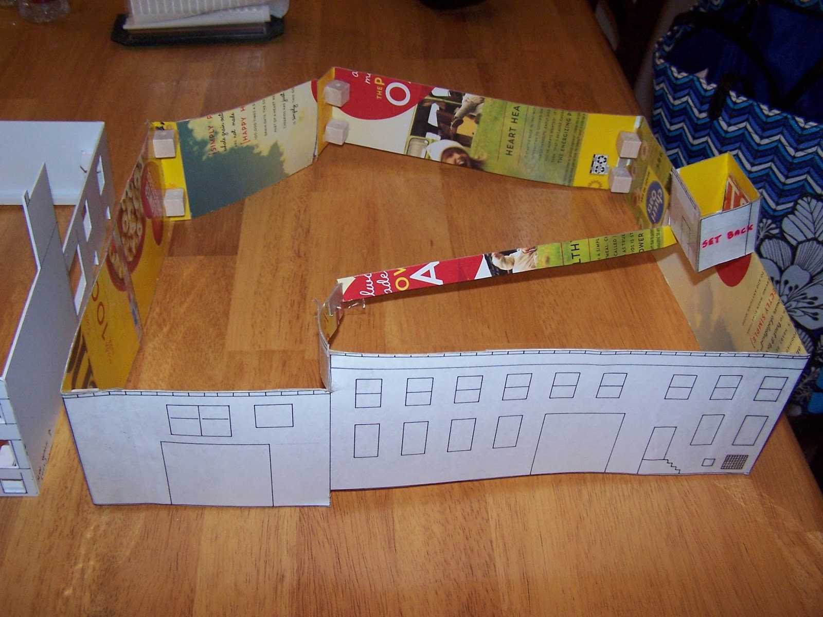
I love making drawings and find it very relaxing and enjoyable, but will gladly take any printed drawings from books or magazines if available. Then, consistent with good advice I have seen online I copied my drawings and glued them to cereal box cardboard. These were then trimmed and taped together to give me a three-dimensional view of the building. Since mine had complex roof lines I left them pretty much open for now. I used wooden blocks to reinforce the corners but they didn't work all that well. 

Then, I waited. And waited. And waited some more until my yearly vacation came around. I didn’t want to start this project and have to stop and put it away every night because of other things, so I just thought about it and collected supplies (like styrene and brick sheet) until the magical week arrived.

For this structure, I plan to use a core of 0.060” styrene sheets. I would have preferred 0.080” but my hobby shop had a lot of trouble ordering it. The down side with going thicker is that when you scribe and snap it the edges don’t always come out square. Also, window openings are more difficult to cut in larger styrene. The walls will be braced in the corners and edges with 1/4" square styrene rods. Additionally, I made some custom 90-degree corner braces from styrene.

Finally, the outside will be sheathed in plastic brick sheets. I looked long and hard online and the various options out there (including some marketed for N scalers) and for right now settled on some by Plastruct. This will be discussed more in the future, but suffice to say that because the sheets are so thin all of the rigidity of the building must come from the styrene core.

Cutting the Walls
One of my favorite tools is my large plastic cutting board which was sold for using in the kitchen for carving turkeys. I don’t have one of those healing cutting mats, but instead have multiple plastic cutting boards in various sizes including a really helpful one about the size of a business envelope. I also have a piece of glass that I sometimes use for complex gluing jobs because styrene won’t bond to the glass. One side also has a "juice" channel around the edges which catches round things like springs and knives from rolling off. (Note: they can warp in the dishwasher from the heat so don't use an old kitchen one if you need it to be perfectly flat.)

I cut the walls to size per the plans, and constantly double checked my work. It is important to make sure the walls end up square and true but even more so when you are scratchbuilding a model and don’t have pre-molded guides. And, since this was to be a model for competition and wonky walls would surely result in a bad score. Inside joints were braced (perhaps too much?) with the square styrene and my corner braces. Since the roofs would be supported along the top and I wasn't sure yet how I was going to do it, all braces were left off the top 1/2" of the model for now. I also made sure not to put any braces in locations where they would be seen from the windows or open doors.

I use Plastruct Weldene exclusively for all styrene joints. It is labeled as non-toxic and I don’t get headaches like when I use MEK, though proper ventilation for everything is a must. I flow the Weldene into the joints on the inside and let capillary action suck it into the gaps. Joints set quickly and fully harden overnight. Usually, I glue up a joint and then let it sit 30 minutes before doing another. If you get it on painted surfaces it doesn’t damage them or cause them to bubble… it will cause the paint to go from shiny to dull, but a coat of Dullcote over it at the end hides all mistakes. I love the stuff, though my shop doesn’t carry it anymore and I have to buy it online. The only downside is that it won't work on ABS plastic, only styrene plastic. 

For the few windows and doors that I have I decided to depart my my usual course and purchase a "Nibbler." In the past, I either did the "scribe an outline, then scribe an X" to break through the plastic or else cut the building into slices, removed the window areas, and then glued it all back together. Here, I purchased the Nibbling Cutter from Micro-Mark (http://www.micromark.com/nibbling-cutter,7761.html) after reading some good reviews online. It is only recommended for plastic up to 1/16" thick (0.0625") and it did a good job on my 0.060" walls. Had I gone with the thicker 0.080" walls, I don't know if it would have handled it. True, the Nibbler is a slow tool to use but it is accurate and sort of fun.


To use it, I had to drill a 3/16" diameter hole inside the window or door area and then begin nibbling out. What I did was to nibble to one of the edges, then turn the tool 90" and nibble along that edge. At a corner, I turned the tool and went on again. I left barely a sliver of plastic at the edges so that a file would straighten it. However, if I were using window castings that sat proud of the wall and covered the edges this might not have been necessary. My windows are recessed in the gaps so straight edges were critical.

Some doors were actually cut out with the nibbler and then styrene was glued directly behind them. That is because I wanted to door to be slightly recessed so I had to make a gap for it, but at this time I didn't want to leave that much plastic missing which could compromise the integrity of the wall. As long as my finished recessed door is less than 0.060" thick it is fine.

The walls went together fine over the course of about 2 days with only one issue. One of my drawings was 3/16" shorter than the opposite side wall, and that resulted in a warped structure. It was easy to correct by sawing through the wall and then gluing another wall piece of the correct length over it. I chose to do it at the short wall section because doing it there wouldn't affect any window or door spacing. I used my Dremel to go right through all of the corning bracing and then shifted it out. The inside is now looking pretty ugly at that corner, what with all of the bracing. However, it won't be visible from the outside. It will serve as a valuable lesson though!

After getting this far, I decided to call it quits. I still need to figure out the divided roof areas for the larger "room" on the right in the picture above, and I don't want to rush it and make a mistake. Also, the small building on the roof and the chimney will also require some thinking to make sure they come out right. Overall, though, I am quite pleased with where it is right now.

Thursday, October 1, 2015

Structure - Albany Tomato Company (part 1)

Where to begin? Humm... 

The Albany Tomato Company (ATC) has been on my mind for several years now. In fact, I have already starting building a model of it (the first model for my future layout) even though in all likelihood the LDE that it will be part of won't be built for many years. However, I will get to my motives later.

The ATC is located at 10 DeWitt (sometimes spelled "De Witt") Street, Albany, NY. It is located north of the Central Warehouse and is around mile post 0.5, which is just at the beginning portion of my layout.

Meeting Len Kilian
Living in the Capital District of NY, our library system is full of regional railroad books and one of them is Trackside in the Albany, N.Y. Gateway 1949-1974 with Gerrit Bruins, authored by Len Kilian and Jim Odell. I had borrowed the book from the library on several occasions and thought very highly of it. Despite the fact that it leaned heavily on the NYC/PC era (railroads that while interesting I cared little about) there were also good sections on the D&H and Rutland. It was fascinating to see the pictures from the fifties and sixties because many of the landmark structures were gone, while others existed in various stages of decay. But, one in particular stood out...


On page 86 was a picture of the Albany Tomato Company as it existed in 1963. Though nearly all of the other pictures in the book were of older brick or stone buildings or rundown warehouses or stations, here was a gorgeous red building with a colorful mural on one wall. The caption said it best: "Most model railroaders are forced to accept selectively compressed versions of industries on their railroads... this June 1963 photo offers a prototype for all of those industries." I was smitten. I did some research on the building and found out that it still exists and, unbeknownst to me, I had parked in front of it many times without realizing what it was. Its current appearance doesn't look at all like it did then so perhaps my ignorance is excused.   

I didn't think too much about it until I went to a train show where Len Kilian had a table of books for sale. I didn't know him or recognize him as the author and thought he was just a regular vendor. I must have been looking at something he had for sale when he asked me if I had seen his Trackside book. Affirming that I had, he motioned me to a small box of pictures for sale that had been made from prints of the book. Without looking, I quickly replied that I was interested in only one picture... the Tomato Company picture. "Ahh, the Tomato Company," Len beamed, and at that moment our friendship began. He didn't have that print for sale at that time but said that he liked it very much himself. After discussing it with him for a bit, I likely purchased something else and moved on. He was, and still is, an active book seller and is always very busy at the shows and I didn't want monopolize all of his time. 

Since our first meeting I am glad to say I have come to call Len a friend. He is a wealth of knowledge about the local rail scene, is always on the lookout for various books I might be interested in, and over time has allowed me to purchase some pieces of his collection at (I am sure) a great discount in part because of his belief that I will be a good steward of the items. Len is quite aware of my ambitious endeavors in modeling this building. In one of our follow-up meetings, he presented me with a very nice print of the picture that had been made from the slide, which is currently framed at home. I am elated to say that recently he sold me the slide of the ATC that was used in the book!

Looking south-west in 1984.
From what I have been able to research online, the ATC would purchase produce from across the country and have it shipped in by freight cars. Then, it would be sold wholesale to various local companies such as grocery stores and restaurants. An obituary from The Troy Record newspaper (4/02/1966, page 14) contained a notice for Gaetano Scafidi, President of the Albany Tomato Company, and it said that the ATC also had a presence in the Menands Regional Market (an area I
am not sure about modeling). I have advertisements from 1951 and 1969 which evidence that they were still in business then, but I don’t know when they stopped receiving rail cars or when they finally went out of business. From my pictures from 1984 the rail siding had been removed and the ATC slogan was painted over, leading me to believe it was not a vegetable wholesaler anymore.

Currently, it is used as a facility for medical treatment as part of the Whitney M. Young Health Center system. And, if one were to compare it to the photo above they would see that the bricks are gone, presumably covered by a concrete or stucco facade. The large truck doors have been replaced with smaller ones, and some new windows on the left portion were added. The ground also doesn't appear very much sloped here, likely a result of adding more earth before installing that concrete sidewalk.   

Modeling Notes
It is an interesting building from an architectural standpoint because it is built on a sloping foundation. Not only that, but the main portion of the building has three different roof elevations and at least two of them are divided not by a straight line but by a “z” shaped line. So, modeling it will be a challenge. I have one shot from 6/1963, several blurry shots showing the north and west walls from 1984 taken from the tracks, and many photos as it currently stands today. The building's exterior in 1963 was brick but now it is sheathed or covered in concrete, though many original window locations haven’t changed and allow for registering what it looked like in 1984. The south wall abuts an adjacent building which I likely won’t build for lack of space. The garage which extends off of the north-east wall may or may not be built.

By 1984, a wooden wall had been erected.
Since the wall with the tomato slogan is the "western" wall, away from the layout viewer under normal layout viewing conditions, I plan to model that wall as it appeared in 1963 and the remaining three walls as they appeared in 1984. Admittedly this isn’t a normal thing, but it isn’t that much different from when modelers painted boxcars with different roadnames on each side to get double duty out of them. If I modeled it as it appeared in 1984, it would make for a boring building. At least by 1986 someone had put up a fence.

The garage in 2015. Note the building on the left, which isn't
being modeled but also would make for an interesting structure
After taking many pictures of the building and also saving online satellite photos, I was able to draw up plans for the structure. I take great pleasure in sitting at a table and making diagrams and sketches, always in ink. I do this for buildings I may never even build. The planning stage is just as engaging as the actual construction. For my plans of the ATC I decided not to compress it in size. The attached garage was also drawn to scale but it is just too large for my layout and likely will be omitted or severely shortened with a black "wall" where it meets the fascia. Having no good pictures of the garage from 1984, I had to guess what it looked like but it probably hasn't changed much since 1984.

For added modeling interest, I plan to build a shadow box scene on the west side and will leave the boxcar loading door open so that I could detail the interior of the warehouse. This will be entirely freelanced as I have no pictures of what the interior actually looked like. 

I have several goals for this building. First, I want to make an accurate representation of the building as it appeared in the book and for that I will need to hire someone to custom make decals or the like from the original slide or a sharp scan. Second, I am planning on trying for my Master Model Railroader certificate in structures (http://www.nmra.org/structures) and this will be my first building towards that goal. I am pulling out all of the stops with this one, scratchbuilding everything possible, and hoping to earn a good score. That is part of the reason I am allowing the option to build a partial shadowbox interior. Third, I want to do a great job and make Len Kilian proud.