I started working on the southern half of the building. Most of the core is 0.060" thick styrene that I purchased in a 4x8 sheet. Because I had left it rolled up for so long, it had a slight bow to it and I had to add more bracing than normal to account for that. But it wasn't a big deal. I love working with styrene.

What I don't love are masonry buildings, because they require cutting window and door openings twice (once in the brick/block overlay, once in the underlying core walls) and you have to be more precise with your cuts because the windows don't have overlapping trim to hide mistakes.
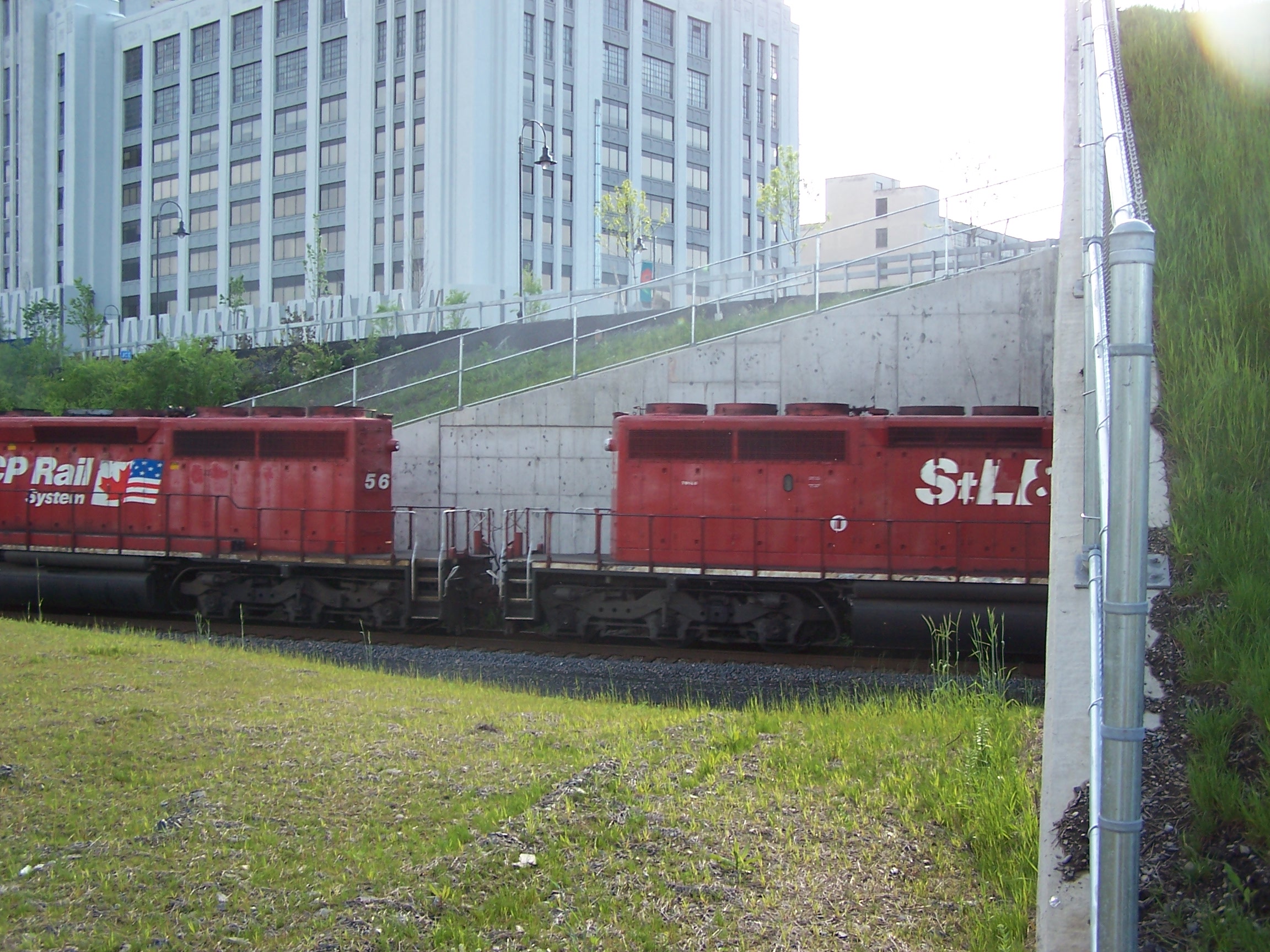
Using the plans I had drawn, prototype pictures I had laminated to protect them, and my cardstock models all as aids, I broke down the structure into smaller assemblies. It started to take over my workbench!

I would first cut the core wall to size out of styrene. Then I would cut some JTT Architectural Model Parts concrete block pattern sheets (#97425) oversize to hang beyond the two ends. This was because I wasn't sure where the corner joints were going to line up. I then opened up the window holes based on the actual castings.

Next, I would set the block pattern on top of the styrene core wall piece and trace out the window openings. These were then drilled, nibbled, filed, and cut out. Finally, the two wall layers were laminated together.

The concrete block material from JTT doesn't feel like plastic or styrene as much as it does a sheet of rubber. It is stretchy and somewhat squishy. It bonds well with MEK, but it is hard to clamp or hold in position without it getting marred. I might try to see if Plastruct has some concrete block pattern if I have to make another structure.
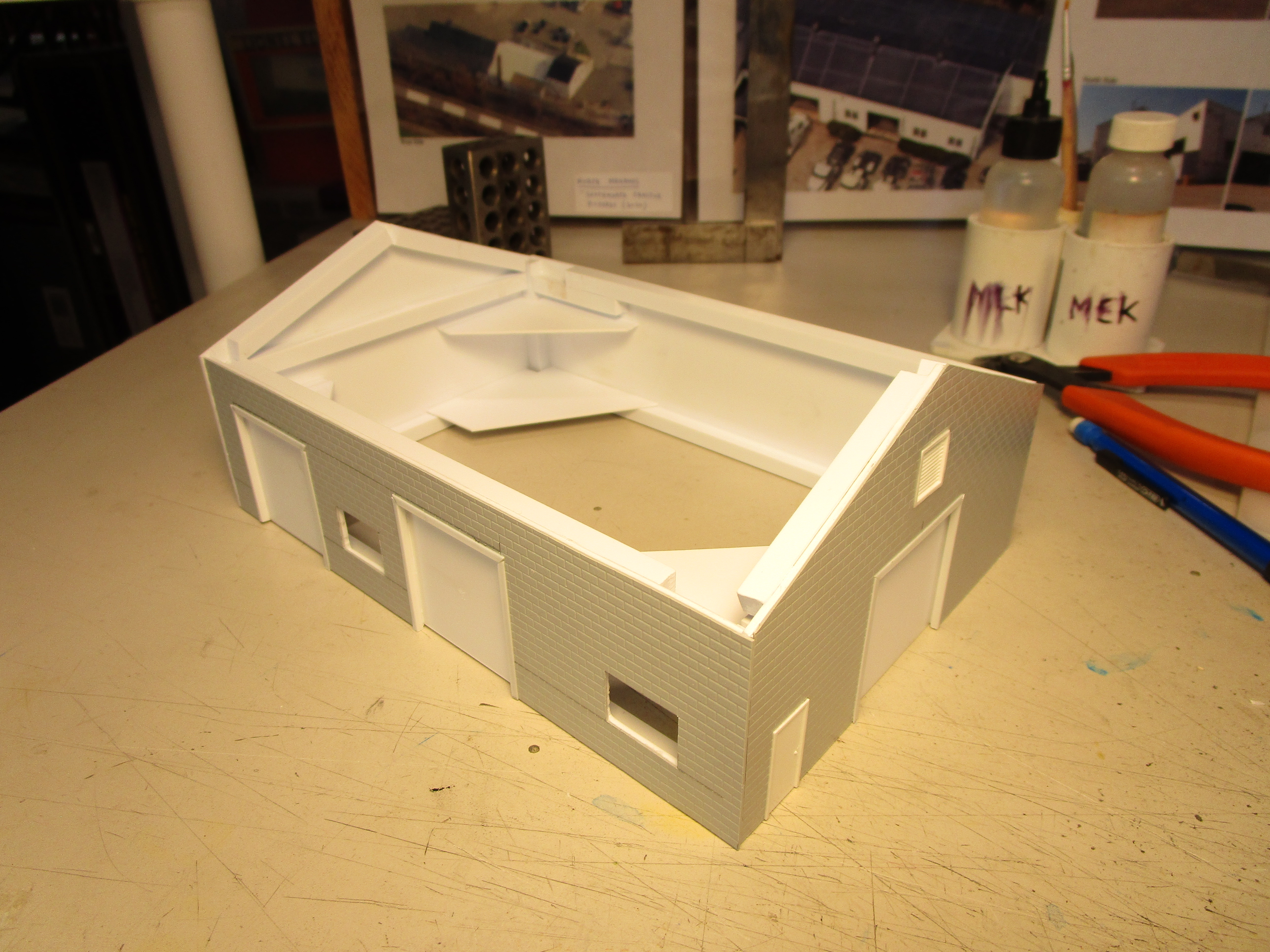
Walls were reinforced with 1/4" square styrene strips, and some triangular corner braces were added. Each room, or extension, of the building was built as four separate walls (with some of the inner walls essentially attaching to one another). I thought that this would be a lot easier than what I did with the Albany Tomato Company where internal walls were sometimes doing double duty for multiple extensions.
I drew a line 1/8" down from the top edge of each wall and lined my upper bracing along this line. Once cured, those braces would support the roof and allow it to drop in place.

When the first part of the building was ready to be joined to the next part, I used clamps to hold it all in alignment.

Sometimes, extra weight was required to keep everything square and firmly in alignment until the glue cured.

After one day, I had two small "rooms" or extensions finished. The roof on the larger area was left off in this photo because I still had to cut the wall facing the right for the entryway door, which was on order. You can see that the paper template has notes to increase the height in one area for the front room, and I had to glue extra length to one section to make it longer. In all, the cardstock templates saved me some from problems later on, and were fun to make.

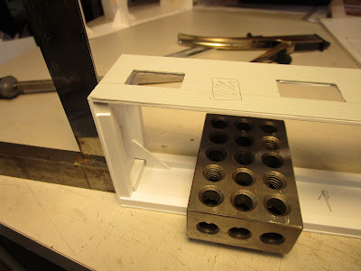
You can never have enough chunks of metal to use as braces, alignment fixtures, and extra clamping weight!

The southern wall was complicated because it used three sizes of window castings and two different door castings. I had to make a simple drawing to keep track of what I needed. That brings up another point: construction was it fits and spurts as I ran out of castings for this and that and had to order more.

The back of the wall showing how I braced it to prevent warping. I messed up with the side vertical braces (they were not supposed to be flush with the edges) and it took a lot of time with a saw and files to remove the unwanted material).

Once the third section of the building was done, I joined it to the previous two.

In my haste I had rushed and assembled one portion of the building without cutting out the opening for the Pikestuff entryway. However, I knew the casting's dimensions and took them into account when bracing the rear of the wall to prevent interference.

The opening was creating using flush cutting pliers and a knife blade. Not very elegant, but effective. Once installed, I could brace the lower edge of the wall

Finally, another portion of the roof was glued on. Because the styrene was slightly bowed I added some weight to flatten it and then applied glue along the edges.

For the rear walls, I didn't bother to detail them like I normally would. That meant no window or door castings, no fire escape stairway, and no intricate trim framework. Those things cost time and money, and there is absolutely no way anyone could see the rear unless I handed them a mirror. It feels like cheating, but I just don't want to put effort into something that only I will know about. All of my other buildings were detailed on the rear, and I did that in case I ever wanted to switch my layout sections around so the back was now the front. But for this, I can live with it. Maybe I will add a door... maybe.
Anyway, here is part of the structure that is facing the tracks. I needed to still trim the block sheet to match the roof profile, then add the roof itself.

Once the brick sheet was cut to the roof profile, I could begin adding some details to the front and sides of the building. These two faces are easily visible so I wanted them to match the prototype. I added some window sill and soffit details (at least that is what I think they are called) from styrene strips. Not all windows had both... some only had the sill. I added downspouts, a couple of vents, and some exterior piping or conduit. There are currently lots of power wires going all over the south side of the building but I may exclude them.

The "middle" part of the building was built the same way. It has no windows to speak of because it is surrounded on all sides by other extensions of the building. As a result, I built it quick and braced it heavily to keep it square.

The roof for all portions of the building was 0.040" thick styrene. I didn't want to use 0.060" because the edges of the styrene would show prominently. If braced correctly, the thinner stuff should work fine.

And by bracing, I used a lot of overlapping, interwoven styrene strips at the peak of the roof to hold it all together. I didn't want to risk it sagging over time. The strips were quickly cut on my bandsaw.

Then, the middle building part was slid into the "L" shape created by the other portions of the structure and secured. That was four subassemblies so far.

Here is what it looked like so far. Construction wise, it is about 40% done. I needed to add the rear portion with the corrugated siding and the smokestack and then the "southern half" of the building would be finished.

I have many friends with 3D printers who are always offering to help make stuff for me, so we looked online to find a find a suitable smokestack to print out. None of the straight, tapered smokestacks worked because they all had brick detail that was much too large for HO scale. So, I went ahead and built it the old fashioned way. Styrene was cut into four pieces, with a slight taper (about 1/16" per side) over the height of 6".

The pieces were glued together with bracing inside the joints, and then it was filled with a mixture of white glue, lead shot, and epoxy (at different times) to make it rock solid. Most certainly overkill! Finally, it was wrapped with Plastruct brick sheeting material (#PS-97) that I had leftover. I really don't like this stuff because the molded brick imprints aren't really sharp and well defined, but it was fine for this project.

When tested behind the building, I noticed the smokestack was a little too large in girth. I wish I had made it slightly more slender. But I will live with it.

The brick chimney sticks out partially from the rear wall of the extension, which was going to be clad in corrugated steel. I first cut the side to length, then held the chimney up to it and marked where it would go. That portion was cut out and the chimney inserted in the gap. Extensive bracing was used because the chimney was heavy.

In the picture below you can see how I braced the insides of the building extension with styrene strips (I ran out of 1/4" square styrene, and it seems most Ebay suppliers have too). The chimney is tapered so I had to cobble together styrene bit around the chimney to secure it. It isn't coming down.

The extension was also cross-braced inside to keep the walls from bowing. The gaps in the cross braces allow me access to the underside of the roof to glue it in place. You can also see the extensive use of triangular corner braces. Because styrene is so cheap, I used a lot.

The roof was marked, cut away for the chimney, and glued on. The gaps aren't a problem because the roof still will have something applied later (tar paper?).

I had to use a "special" clamping solution for one corner of the roof. But as a friend says: "If it's stupid but it works it isn't stupid."

The three walls were clad in corrugated steel sheet styrene from JTT Architectural Model Parts (#97402), with an opening on one end for the garage door (which I will paint and add later). Some concrete block sheeting was also added along the top. Because it was easy, I added a Pikestuff door to the rear wall. I couldn't help it... it was too plain looking. The windows I could live without, but a door?

And with that, the southern "half" of the building was was mostly done. Except for painting... and weathering... and installing the windows... and the roof... and final details. The paper mock up was pretty handy in conceptualizing the final structure and checking dimensions.

When set on the layout, it looked pretty good. Astute viewers will notice that the top of the chimney has a lip built up from more brick sheets. I think it makes it look a little better.

Now, on to the northern half of the building...