
My construction had progressed to where things had to be done in a certain order. The walls were bowing slightly inward, and without the roof trusses, there was nothing holding them straight at the top. But I wasn't sure how I wanted to make the roof removable. Ideally, the trusses and roof would be one piece that lifted off but that wouldn't control the bowing. (I had an idea for running thin steel wires across the top to hold them in position, but didn't like it). If I added the trusses, the bowing would cease but then the roof itself would need to be something like metal or cardstock bent into an inverted "V" shape that dropped onto the trusses. Doable, for sure. But then the trusses would prevent easy access to the inside of the engine house for detailing, so I had to finish the interior (including a locomotive) before the roof trusses went on.
While I was mulling that over, I added scenery along several of the edges that didn't require the building extension to be finished. First, thin plywood and cardstock along with some scraps of code 70 flextrack were glued to the base. The ties and rails were then painted and weathered.

Next, the tracks were then liberally buried in real dirt, ground foam of various colors, and a very small scattering of dark gray ballast. Prototypically, this track likely wasn't kept in good condition and I wanted it to look like that. It was all secured with alcohol and glue sparingly using an eye dropper, because too much moisture could be absorbed by the wood in the structure and cause the building to warp.
NOTE: during final model judging I was knocked a point or two because the tops of the rails were left painted "rusty", whereas if this were an active enginehouse the tops should have been silver. Since I had decided to use brass rail instead of nickel silver I had weathered the tops of the rails to hide the gold color. Lesson learned: use nickle silver rail for all projects.

Along the edges of the building where there wasn't much room for scenery required tilting the building at a very sharp angle to keep the glue from flowing off. But, it worked out okay.

I then installed some 2x12 wooden planks along the inside edges of the stone foundation. This not only hid the vinyl wall joints but also created a nice ledge that would be perfect for adding details onto.

I wanted this structure to have a detailed interior, and having been inside actual steam engine houses I knew that this meant lots of bits and pieces here and there. So, I raided my HO and N scale parts boxes and took out every crate, barrel, freight car and locomotive part, bench, and anything else that might work. Dozens of little things that individually might not make sense but once painted and logically placed would give the feeling of a busy maintenance building.
I also went to the local hobby shop to purchase a junked steamer, and in the process found a bag of loose detail parts for $5. Score! Everything in the picture cost less than $20, though I ended up not using the tank car.

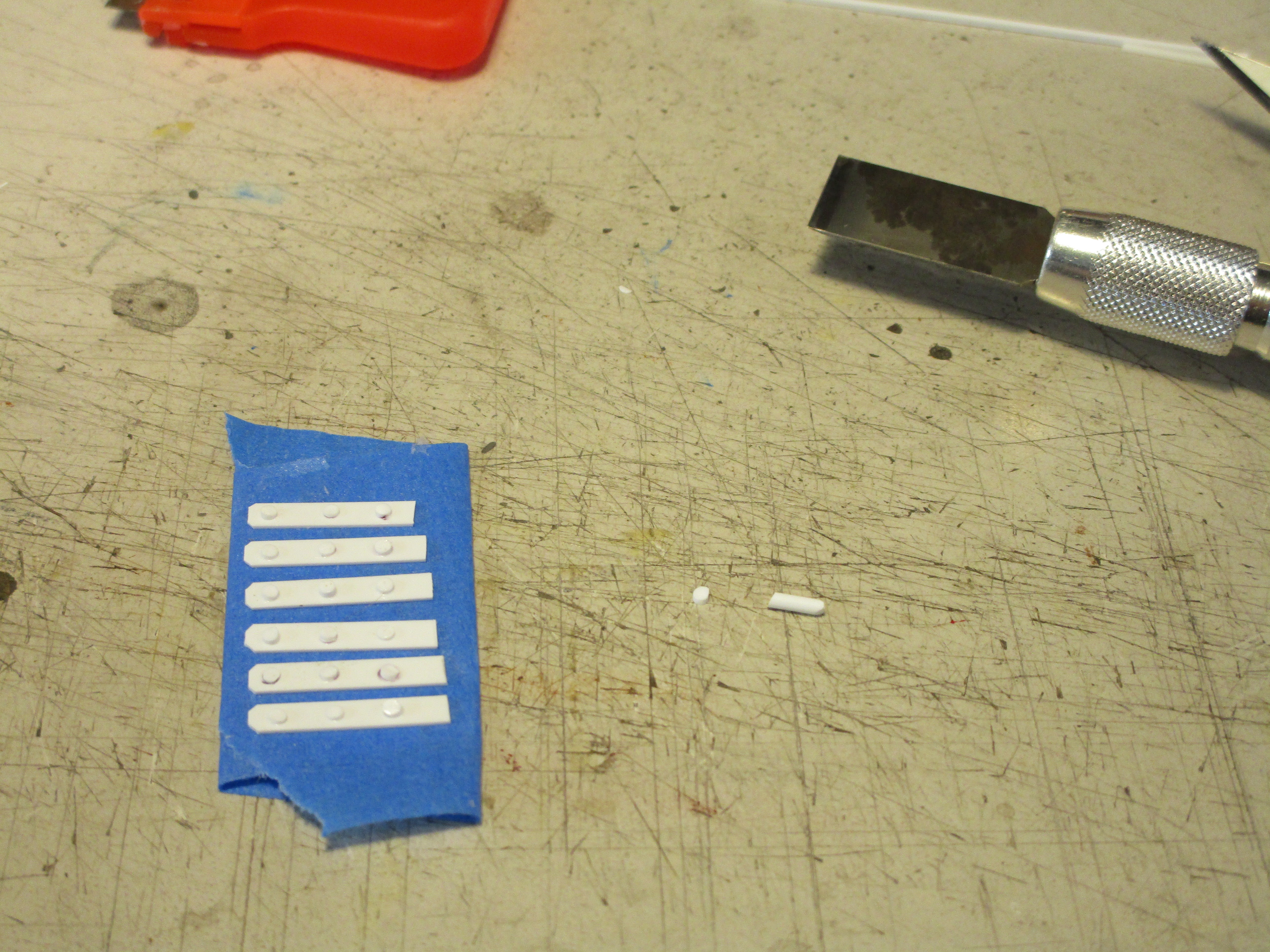
Inspired by a casting I saw for sale on Ebay, I decided to make my own pair of workbenches. I used an HO scale figure to rough in the dimensions, and added rectangles (for drawers) and slivers of styrene rod (for knobs) to the front.

Then, they were painted and I highlighted the knobs with a contrasting color.

Once suitably laden with various parts and pieces from the aforementioned scrap piles, it became a realistic workbench. I will repeat sage advice passed on to me in the past: never throw anything away!

The original Model Railroader article suggested using an old Walthers "blacksmith" car for parts, which is exactly what I did for a couple of items such as the hearth and the anvil which you can see in the pictures below. The flatcar itself was set aside for now.
Here is what the interior looked like with all of the details in place.

From the other side. It sure is busy looking, but I think it looks pretty good.

The engine was a challenge. I wanted a "shortline" or "backwoods" type of steam locomotive, but after searching at several trains shows and hobby stores in the used/broken bins I couldn't get anywhere near a Shay or Heisler for less than $100. And that was too much for something that would just sit there as a static model. I found lots of 0-4-0 tank engines and larger Hudsons or Pacifics but they were either too "cute" or too big for my line. Finally, I found a broken Bachmann 0-6-0 engine and Riverossi tender that I matched together.

I took both apart and removed any weights, motors, gears, or unnecessary internal wiring parts to lighten them up. Then, I superglued them shut and also locked up the wheels from rolling. After that, they were washed with soapy water and left to dry. A coat of flat black was followed up with some weathering. I piled the tender high with a load of real coal, which perhaps should have been lumber because it was a logging railroad. I didn't bother to superdetail them though because the locomotive isn't the focus of my structure. Sadly, at this point I realized that the engine was too long and wouldn't fit completely inside the engine house. Doh! Perhaps the engine house was sized for a small logging engine without a tender.

The decals were custom made by Bill Brillinger at Precision Design Company, and I chose a font style that seemed appropriate for a logging engine. They would have looked better on a shay than an 0-6-0 switcher, but what can you do? By the way, the name of the railroad is an inside joke. It contains the two last names of the NMRA judges who have been reviewing my models for my M.M.R. certificates. They really like wooden structures, so I thought that naming the railroad after them would be apropos. The number "13" was because this was my thirteenth scratchbuilt structure for the award.

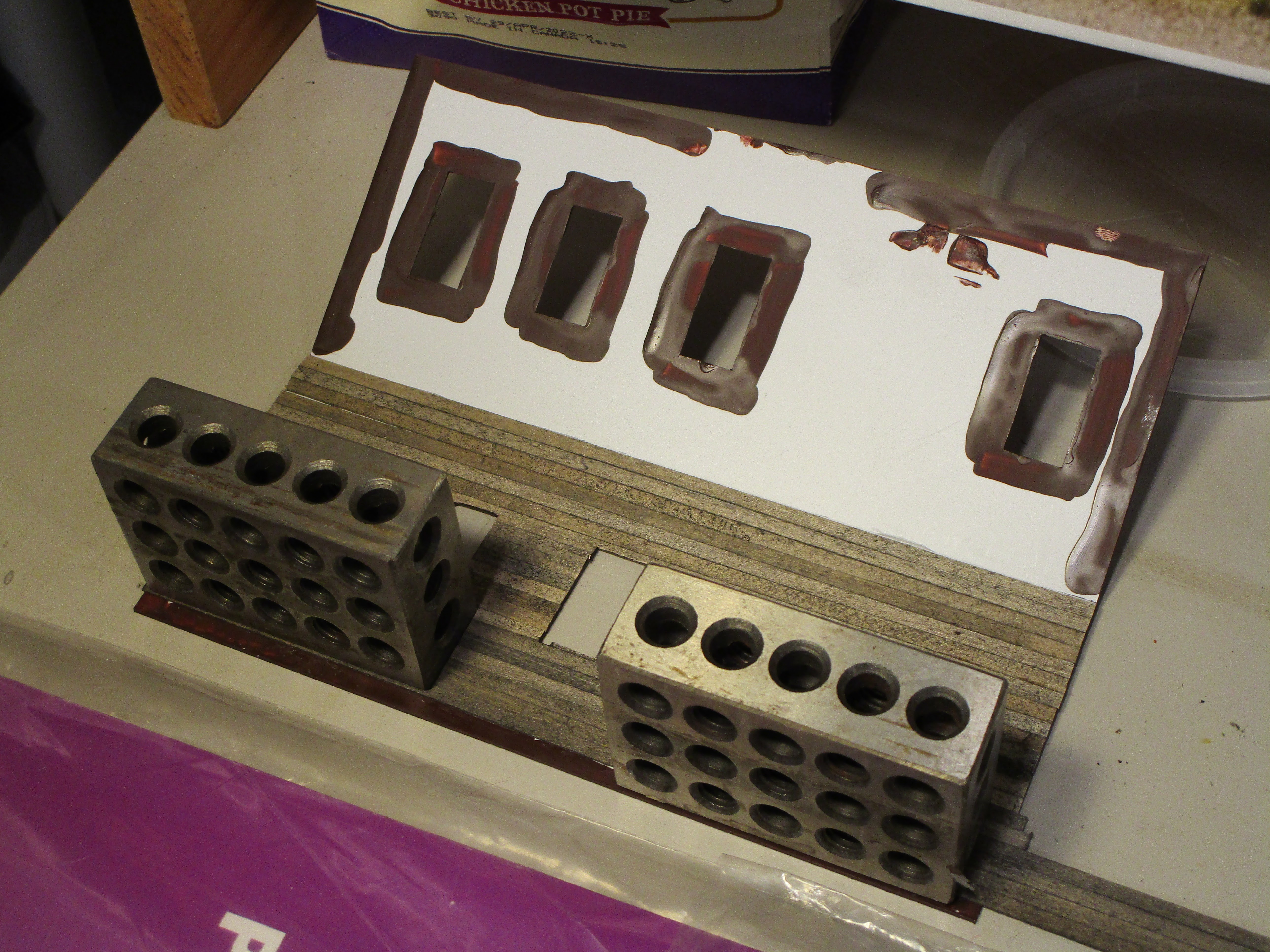
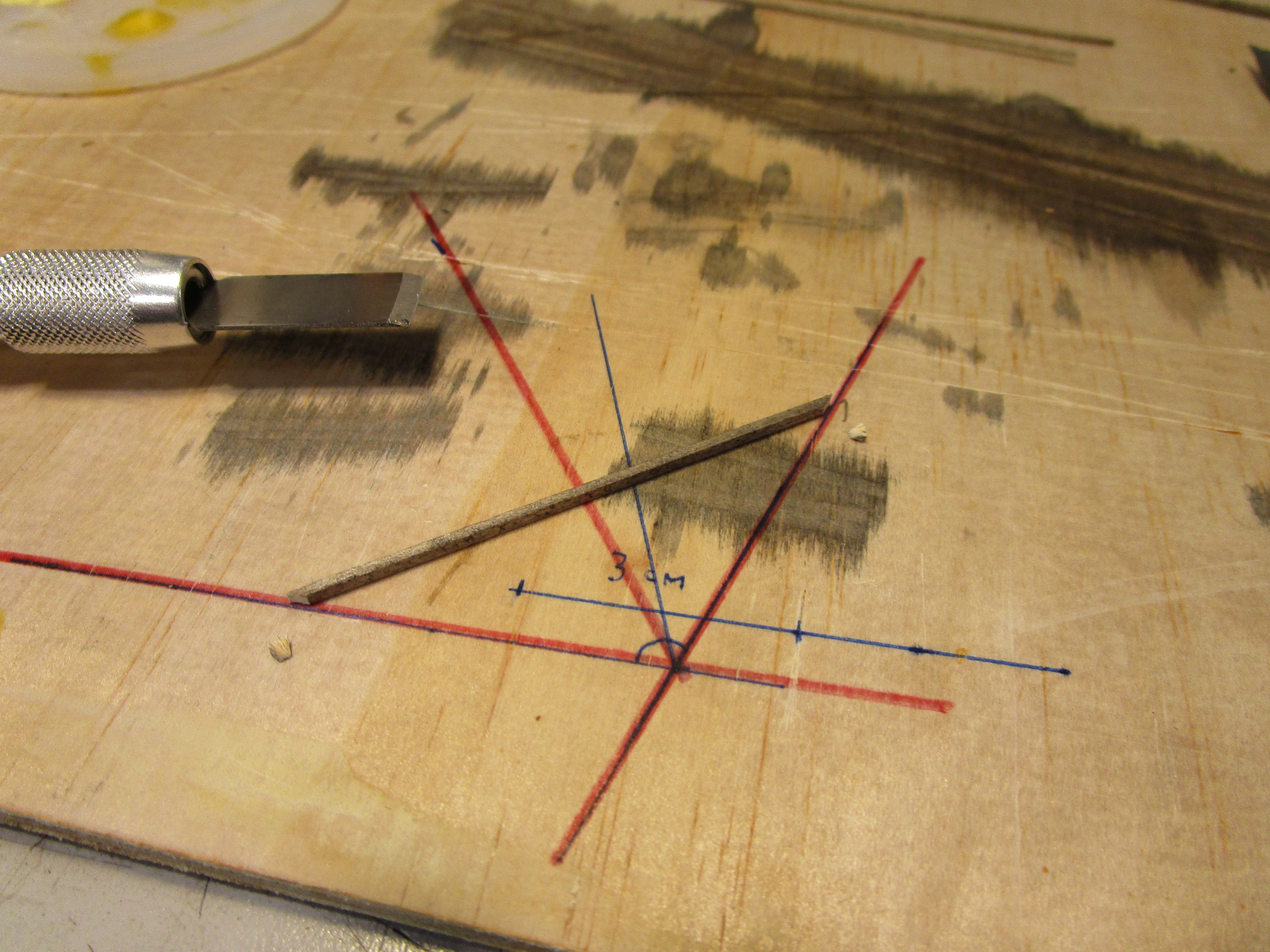
If you are wondering what those green wires are for, they are to secure the locomotive inside the building. They are thin, steel floral wire. Using a custom wooden template, I marked out the locations on the engine house floor where I had to drill holes for the wires to pass through. After they were drilled, I used a larger bit on the underside to open up the area... sort of like countersinking the hole.

The wires were fed through the base and then bent and stapled temporarily so the engine wouldn't fall back out. I checked to ensure all the wheels were on the rails, and then I flipped everything upside down. Two-part epoxy was poured into the holes, filling up the countersink space and really surrounding the wires. Then, I covered the holes with blue painter's tape and flipped everything right side up. Once the epoxy cured later, I peeled off the tape and cut the wires flush. The engine was now there for good... the last thing I needed was to have the locomotive become unglued from the track and bounce around and knock out the delicate walls!

No engine house wouldn't be complete without its doors, so they were next. As noted in the first post, I had to remake them larger than the first pair to actually cover the door openings instead of sit inside of them. I used 2x6 and 2x8 lumber to make them, and oddly enough discovered that Kaplan and Northeastern Scale Models lumber is not the same dimensionally even though both sell stock labeled "2x8". The plans called for hinge castings from Campbell Scale Models. That didn't seem like much fun, so I built them myself from pieces of 0.020 x 0.125" strip styrene and and 1/16" styrene rod. Bolts were added using slivers of styrene rod that were then sanded down to minimize their height. I just wish I had remembered I had a stash of nut/bolt/washer castings because they would have worked great! The hinges were attached to the doors with superglue.
If you are wondering "Hey, don't you need 12 hinges instead of 6?" you are correct. I didn't think of it until I had mounted the fifth hinge to the door and realized I had only made half the number required!


The trusses were based on pictures found in the article, and they were pretty fun to build. All told, each one took about 15 minutes to make. It was the perfect project to work on while listening to a football game on the radio.

When I test fit one in place, it fit perfectly.

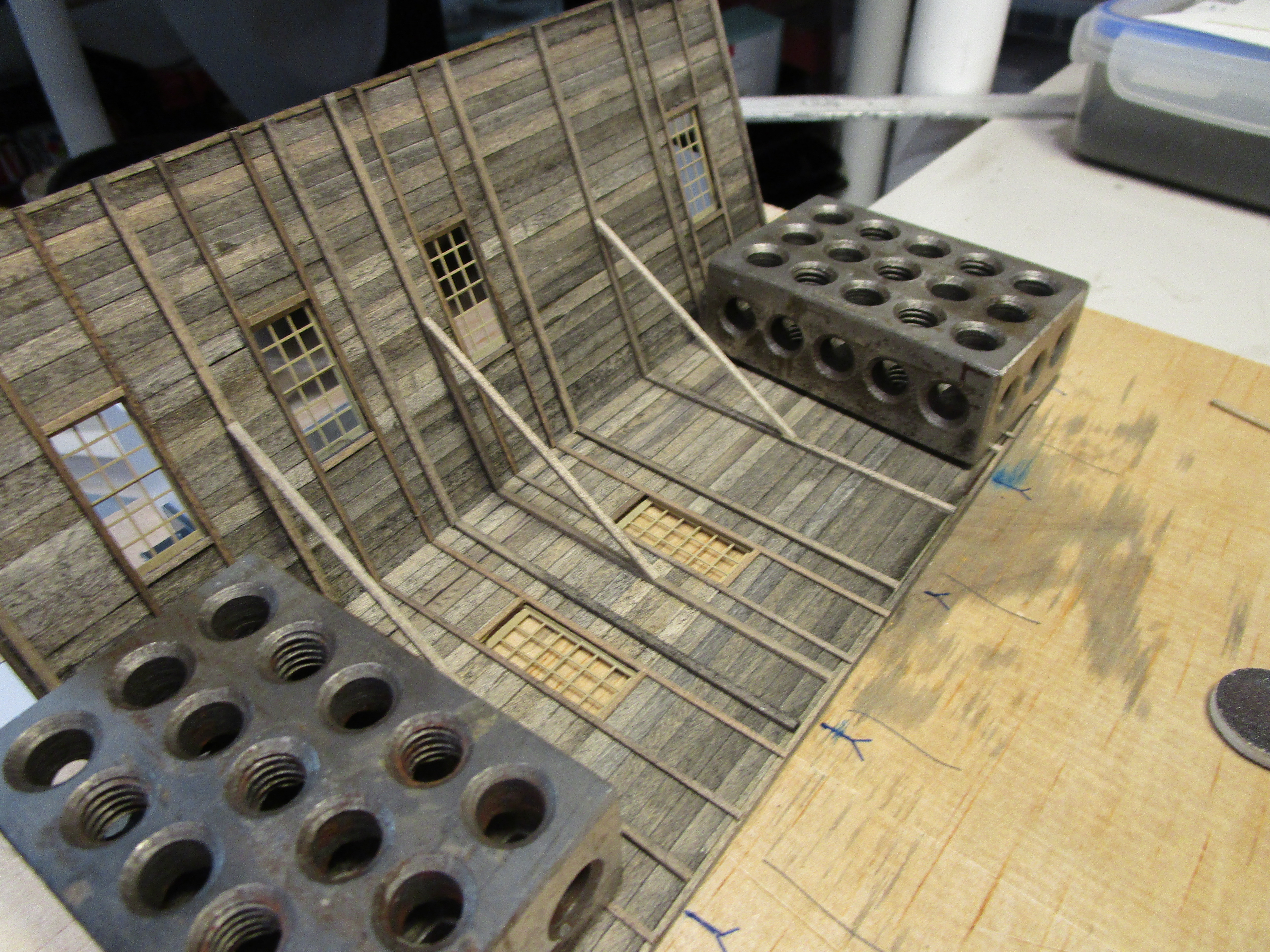
Of course, something needed to hold up the trusses. The plans called for a center longitudinal beam supported by four posts which ran down the center of the engine house. I built another jig of sorts which really only consisted of a backstop so that I could push against the wooden main beam without it flexing. The four posts were glued it in place and aligned along the drawn lines. Then, the diagonal support braces were installed. Everything was left a little longer than required, because I would trim them to size during installation.

Once the glue cured I used a wire brush to remove any excess adhesive residue.

The areas of the engine house floor where the posts went were marked with a pen.


Installing the shingles took a long time. I tried for nice neat rows but it was near impossible because the length/height of the shingles was all over the place. If I ever try this again, I will strive to cut them to more uniform dimensions on the paper cutter. I also realized my initial method of installing them with tweezers was not only tedious but it also left a gap on each side where the points of the tweezers were. I initially thought this was good, as all shingles have spaces between them, but after the first row I realized it was too large a gap.

I then switched to the method included on the instructions provided with the cedar sheets: stab each shingle with the tip of a knife and lay it in place onto the glue, holding it firm with something else (I used a toothpick held in my other hand) while the knife blade is pulled away. This worked great, went quicker, and didn't leave gaps between the shingles. Lesson learned: follow the instructions.
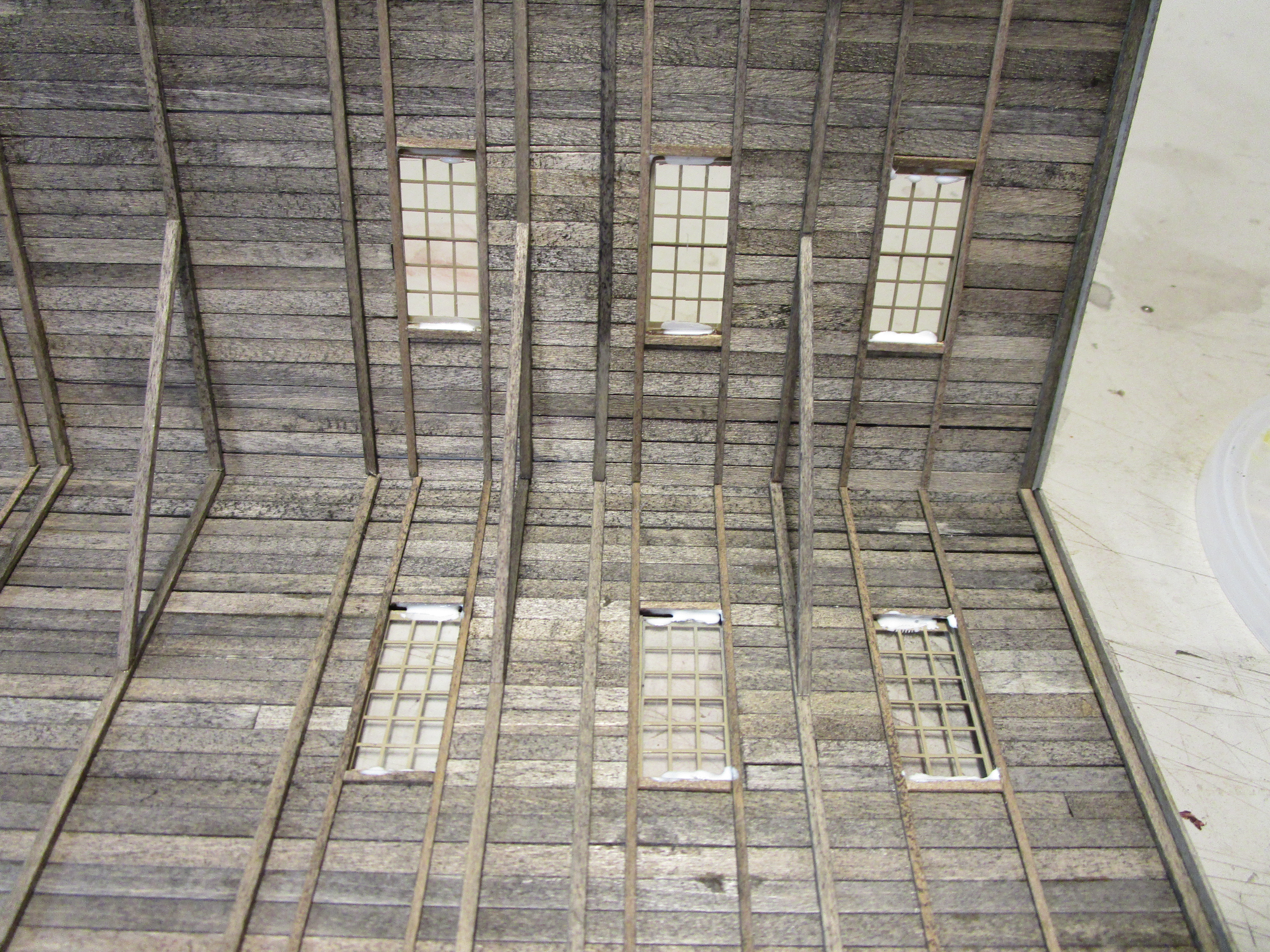
Shorter shingles were used under the skylight castings so that their wooden frames were not covered.

You can see in the picture below how the bottom of the newest row is pretty straight across, but the tops of the shingles are all over the place in terms of height.
As additional rows were added, humps in the shingles where they had to go over each other started to form. While it added character, I minimized it by using weights to hold down the shingles while the glue cured.

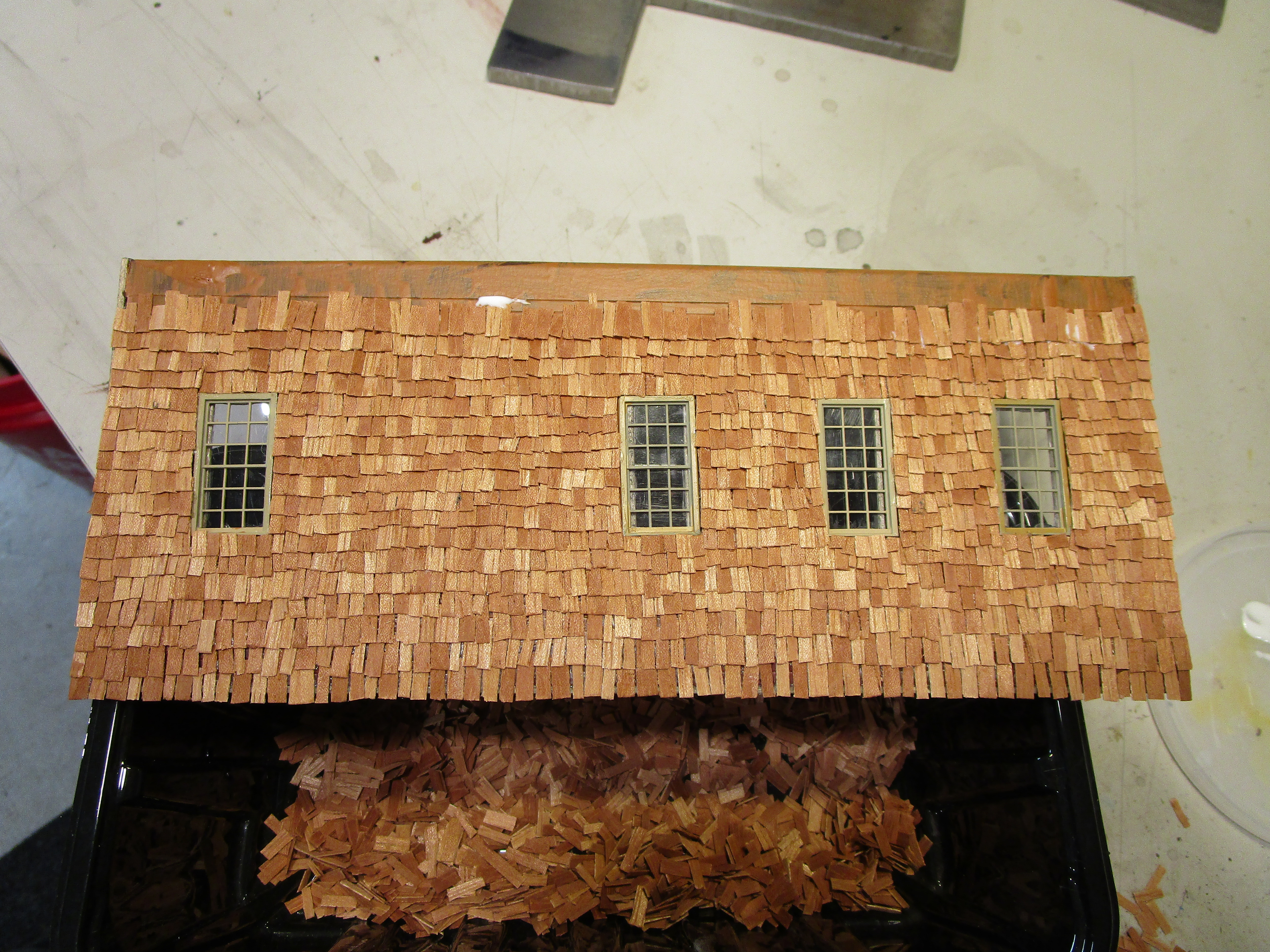
Finally, one side was finished! I let the tops of the very last row stick up a bit and once the glue cured I cut them flush and gently sanded the the row flat. I am not sure yet how I will handle the roof peak.

Until next time...
No comments:
Post a Comment