
Before starting the northern "half" of the building, I looked at my supplies and realized I was dangerously low of the concrete block pattern sheet from JTT as well as styrene 1/4" square strips. Ebay seemed to be out of them, so I ordered directly from Evergreen. It was at this time I found out about their bulk pack of them (15 pieces, instead of the normal 3 per package). Score! I ordered two packages, just to be safe. They will last a while.

I decided to only make a drawings of the footprint of the northern half and not do any side elevation drawings. While this turned out to be much quicker, it also led to an error that I have to live with in the final building. The length was shortened intentionally and that resulted in omitting one entryway and one window.

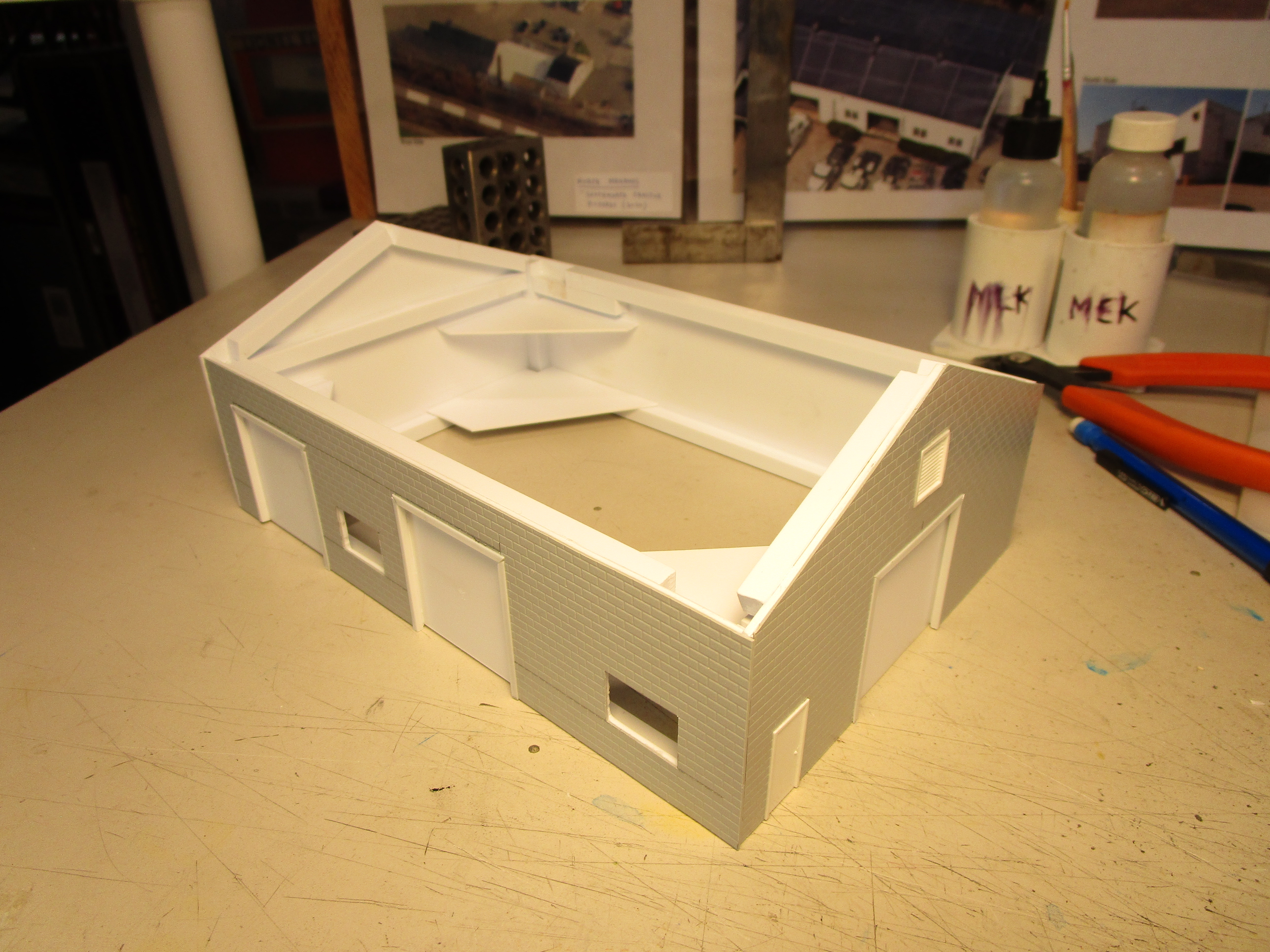
The usual two-ply wall assemblies (core wall of 0.060" styrene, with brick sheet laminated on) were used. For the roll-up garage doors, I framed the openings with styrene L-angle and then slide some O scale freight car siding oriented so that grooves ran horizontal behind the angles. They look just like roll-up doors and I could build them to whatever size I needed (instead of depending on what castings are available). The louver above the end door is from Pikestuff and I used it only because I had it my parts bin.
To join two building portions together, I used a trick I learned from Model Die Casting. I drilled hole between the two buildings similar in diameter to some styrene rod I had on hand. Then, I made "washers" from scrap styrene and glued them onto the rod. These were inserted into the holes from one side and additional styrene washers were secured on the other size. Once cured, the joint was rock solid. This plastic nut/bolt assembly is what MDC used to attach weights to their freight car chassis kits. I could have used real nuts and bolts, but this seemed more fun.

The roof was installed and braced again with interlocking braces. On the end are three rectangles of styrene with rods coming through (and cut off). Those are one-half of the styrene weld-bolts that join the two building extensions together.

It still needs the roof covering applied, but I add that after painting the body. Note that different roof pitches where the extensions join, which matches the prototype. It looks odd, but that is what they did. It certainly adds character to the structure.

The last part of the building extension was sketched up by placing the building on the drawing of the base I had previously made, and then adding lines where I wanted the new portion to go. Pretty scientific...

The extension has a roof picture different from the three other parts of the building it joins to. They are close, but not exact. Or maybe it is just sagging. To get it right, this time I used poster board mock-ups to check various dimensions. Again, prototype pictures shown in the background aided me immensely.

The north-western extension was built as three walls which I aligned on graph paper with the rest of the building and then connected with styrene braces. Crude, but strong.

The poster board had one use left... to mock up the styrene roof.

With that, the building was finally finished. I still need to clean it, paint it, decal it, weather it, apply the roof treatment (likely more tar paper), roof details like vents, paint the windows, paint the doors, etc... but at least the structure itself is finished. I really pushed myself to get this done, because my future schedule is likely going to change and free time will be but a memory.

When placed on the layout, it looks a lot larger than I expected. But I really like it. The track switch ground throw controls are in awkward spots but that is okay... there is only supposed to be pavement there anyway. I need to build up a foundation for the building from sheet cork.
A view from the rear, which is only possible because I took the backdrop down. Boring...

No comments:
Post a Comment