It seems that I get sick every February or March. This year, I have the flu. It isn't fun, but I seem to be getting better. Unfortunately, a couple of weeks ago I ordered enough code 83 Micro Engineering flex track to finish the main line on the layout. But then, between other priorities and my illness it has just sat around mocking me. Thankfully, I am feeling better and hope to get on with my layout.
I also began work a couple of weeks ago on another G gauge gauntlet track. It was going well until I ran out of rail (again!), so I had to order another 6-foot long piece. And so that project is hogging up my work bench.
CP Executive train in Albany

Friday, March 16, 2018

Sunday, February 25, 2018
NMRA challenge: Scratchbuild something!
A week ago our Hudson Berkshire Division (of the NMRA) held its montly meeting, and instead of a layout tour or clinic we were told in our monthly newsletter it would be a "scratchbuilding night." Inspiration for our meeting comes from the Carolina Southern Division and their Program Chair, Scott Perry, for helping our Vice-President, Irwin Nathanson, prepare for and lead our meeting.The information that we were given in advance is:
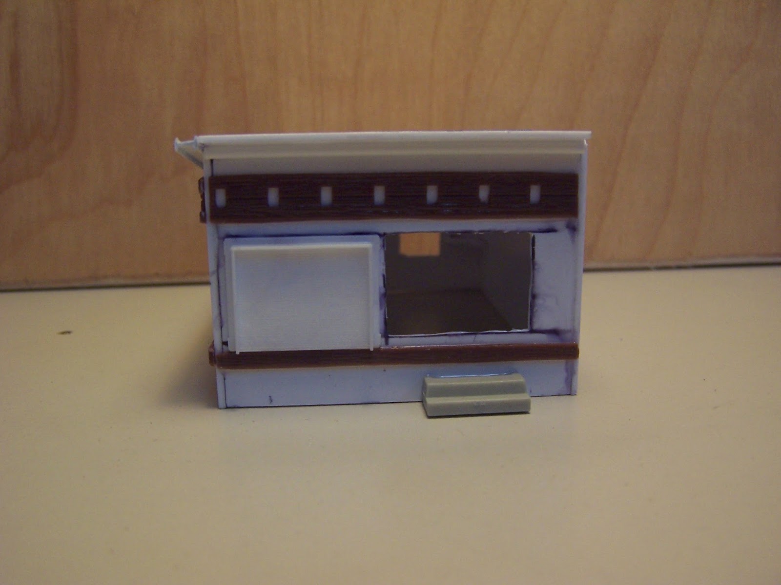
 Since I like scratchbuilding in styrene, I got pretty excited about this. I thought about what I might want to build, and focused on a hot dog grill shack like one might find in the Lake George area. Though they are sadly becoming a distant memory, they are frequently decorated on the outside with gaudy trim, whatever else might be lying around, and usually showing the effects of winter's neglect and seasonal financial constraints. The shape and design though was heavily influenced by Gus's Hot Dogs, a small dive place in Watervliet with an open window front wall and marginal seating capacity inside.
 I brought two brand new #11 blade Xacto knives with me (along with more blades in case others needed some), a metal engineering square, a corner nibbler, a plastic kitchen cutting board which I have used for years for modeling, and my own small bin of styrene scraps. When we started, we were invited to come up in rows and look through the stuff and take things. I took one sheet of 6" x 12" styrene (I think 0.040"), and one HO door casting which I used to base everything else from. After a couple of sketches of raw dimensions on some newspaper, I started cutting and gluing.
 I knew this model would not end up on my layout, but I did want to keep it and treasure it so I took the challenge seriously. I laid out the four walls and then used my knife and nibbler to cut out the window and door areas. I glued up the four sides and braced them with triangles of styrene on the inside, and then attached the door casting. Another trip up to the spare casting bin (after everyone else went through first, to be fair) yielded two odd window castings, a couple of flower pot details, and something that looked like a flat vent. I also found some odd brown patternwork that when sliced into strips resembled the bric a brac found on Lake George area buildings.
 I wish I had the time (and file) to clean up the window openings better. The roof wasn't cut perfectly and there were gaps along the roof edges which I tried to hide with some round trim and I-beam material that resembled a gutter. My pen markings show on the styrene, but painting the structure was out for sure due to time constraints. The rear wall never had windows installed, and one side is blank styrene (but I imagine the grill is along that wall, so windows aren't necessary and all venting is through the roof.
 After about 75 minutes, we had a show and tell period. There was a lot of cool stuff out there. Some people used cardboard and their buildings showed a bit of crudeness that comes with it. Some wooden structures were very well done. There definitely was a corrolary between small structures and more finished results. If you swung for the fences with a complex building, you likely didn't finish it. Had I been forced to use wood or cardstock, I likely wouldn't have been pretty frustrated. I hope to explore those mediums down the road, but learning them for the first time under time pressure without drawings would have surely led to a miserable evening.
 Still, I had a wonderful time and am very proud of what I did. I take these contests seriously. In 2011 our division held a "Pair O’ Dice" contest where we were given several months to build/make something involving dice. Some people took the easy way out and simply named a structure with the play-on-words "Paradise" (lame) in it. Others used dice in unusual ways, such as for switch control markers, or buildings with actual dice somehow involved (casinos, tattoo parlers, etc.). I went off the rails and built a fanciful entire train involving dice, with the piece de resistance a gondola decorated as a craps table. I took second in the contest.
Participants’ instructions will be to simply “build
something” and all will have one hour to work on their creation. Options
include houses, stations, factories, rolling stock, or…perhaps a bridge …see
related article in this issue! Then there will be a “show and tell” so everyone
can show their results and discuss what they built. You can build something
just for this event or something that you might put on your layout. All
materials will be supplied including cardboard, wood and plastic coffee
stirrers, styrene sheets and shapes, bass wood in various forms, misc. metal
tubes and forms and “pot luck” of material from [the host modeler's] Scrap Box that you
might be able to use. [The]Scrap Box is mostly plastic windows, doors, walls
… leftover parts from years of kit building. All HO but, for example, some windows would
work with other scales.
Some limited tools will be supplied. For cutting, this
includes safety razor blades. However, if you prefer, please feel free to bring
your own Exacto Knife (#11 blade) or Scalpel. Newspapers, sandpaper, glues and quick-drying
spray paint will also be supplied. Above all you need to bring is your
imagination! Please do not bring any drawings, photos, plans, etc. The real
“test” of this exercise is not to see if you can scratch build, but rather to
challenge your creativity. Blank paper and pencil or pen for sketching out your
project is acceptable. [Someone] is bringing his HO gauge Scale Ruler. Feel free to
bring your own, especially if you model in another gauge.
 Since I like scratchbuilding in styrene, I got pretty excited about this. I thought about what I might want to build, and focused on a hot dog grill shack like one might find in the Lake George area. Though they are sadly becoming a distant memory, they are frequently decorated on the outside with gaudy trim, whatever else might be lying around, and usually showing the effects of winter's neglect and seasonal financial constraints. The shape and design though was heavily influenced by Gus's Hot Dogs, a small dive place in Watervliet with an open window front wall and marginal seating capacity inside.
 I brought two brand new #11 blade Xacto knives with me (along with more blades in case others needed some), a metal engineering square, a corner nibbler, a plastic kitchen cutting board which I have used for years for modeling, and my own small bin of styrene scraps. When we started, we were invited to come up in rows and look through the stuff and take things. I took one sheet of 6" x 12" styrene (I think 0.040"), and one HO door casting which I used to base everything else from. After a couple of sketches of raw dimensions on some newspaper, I started cutting and gluing.
 I knew this model would not end up on my layout, but I did want to keep it and treasure it so I took the challenge seriously. I laid out the four walls and then used my knife and nibbler to cut out the window and door areas. I glued up the four sides and braced them with triangles of styrene on the inside, and then attached the door casting. Another trip up to the spare casting bin (after everyone else went through first, to be fair) yielded two odd window castings, a couple of flower pot details, and something that looked like a flat vent. I also found some odd brown patternwork that when sliced into strips resembled the bric a brac found on Lake George area buildings.
 I wish I had the time (and file) to clean up the window openings better. The roof wasn't cut perfectly and there were gaps along the roof edges which I tried to hide with some round trim and I-beam material that resembled a gutter. My pen markings show on the styrene, but painting the structure was out for sure due to time constraints. The rear wall never had windows installed, and one side is blank styrene (but I imagine the grill is along that wall, so windows aren't necessary and all venting is through the roof.
 After about 75 minutes, we had a show and tell period. There was a lot of cool stuff out there. Some people used cardboard and their buildings showed a bit of crudeness that comes with it. Some wooden structures were very well done. There definitely was a corrolary between small structures and more finished results. If you swung for the fences with a complex building, you likely didn't finish it. Had I been forced to use wood or cardstock, I likely wouldn't have been pretty frustrated. I hope to explore those mediums down the road, but learning them for the first time under time pressure without drawings would have surely led to a miserable evening.
 Still, I had a wonderful time and am very proud of what I did. I take these contests seriously. In 2011 our division held a "Pair O’ Dice" contest where we were given several months to build/make something involving dice. Some people took the easy way out and simply named a structure with the play-on-words "Paradise" (lame) in it. Others used dice in unusual ways, such as for switch control markers, or buildings with actual dice somehow involved (casinos, tattoo parlers, etc.). I went off the rails and built a fanciful entire train involving dice, with the piece de resistance a gondola decorated as a craps table. I took second in the contest.
Monday, February 19, 2018
Handlaying a Gauntlet track - FAIL!
For my third and final handlaid trackwork piece, I wanted to do something different. And, out of the whole list a gauntlet track seemed pretty easy. I did some online research and found pictures of some examples where gauntlets were used to bring the mainline closer to a station platform or farther away from a station platform to maintain clearances. They only had points, and no frogs. I found other examples where tracks crossed into each other (usually, for different rail gauges) and there were frogs but no points involved. Which was fine, as I didn't really want to make more points or frogs. My switch/turnout and crossing had been educational and fun, but I wanted to push myself to do something different.
 But then I saw a couple of pictures online where tight streetcar track formed a gauntlet to allow it to get around sharp corners where parallel track wouldn't have enough clearance to do so. If you go to this website you can find some interesting street trackage pictures, including the ones posted here. Photos are by Salada from Freerails.com and used with permission. This gauntlet is interesting because it is short, it features curved and straight track, it has guardrails on the track, and it has paved track. There is another picture on the link showing similar track in a stone-paved roadway.
 I had four options for the frogs: (A) I could purchase a chunk of something (brass, steel, aluminum) and mill away the intersecting channels on my friend's mill. It would be pretty easy, as I think I can make both paths straight through the frog instead of curving one. (B) I could buy a chunk of metal but instead use my Dremel tool to cut intersecting slots. This wouldn't be as precise as a milling machine, but it really doesn't have to be either. (C) I could buy some thinner brass and use my belt sander to form four shapes which, once soldered together onto a sheet of brass, would form the frog. (D) I could take two rails and overlap them by cutting away the base of the "top" one and the head of the "bottom" one and soldering them together. I saw it demonstrated on Tim Warris' website (he makes the Fast Tracks jigs) and it looked like fun.
Unfortunately, I ran out of rail. And, LGB rail in 2' lengths might be too short for the outer rails. Aristocraft rail is longer, but isn't manufactured anymore. I didn't want to purchase long (3') lengths of code 332 brass rail for this project, as that will be expensive. So, I instead bought some code 250 aluminum rail from Llagas Creek.. Sure, it isn't the best for track power but for what I am doing it should be fine. And, it was only about $1.50 a foot. The only real downside is that it can't be easily silver soldered, so frog option (D) is out.
 I sketched up some ideas for various radius measurements, and to preserve the look of the gauntlet I had one side curve away on both tracks and the other have one leg curved and the other straight. The radius I drew are extremely tight (about 17"R on the inner one) but my short wheelbase test engine will make it and these were, in real life, very tight. One frog has two straight intersecting rails but the other had a curved rail, which matches the prototype and also will be a bit more challenging (and, in my ignorance, interesting) to fabricate. It would certainly be a challenge.
 So, I bought some 1/8" thick by 1" wide brass bar stock online and drew out some lines to represent where the rail surfaces would be. Then, I cut it apart into four pieces and took each one to the belt sander to clean up. After that was done, I soldered them to a thin piece of brass shim stock and waited for it to cool. And that is where trouble began. I didn't pin the pieces down and they constantly wanted to "float" on the liquid solder and come together into one unit instead of remaining four pieces. I managed to push them around before it cooled, but it was difficult. Final clean up included a bath in alcohol and then a trip under the wire brush wheel. The last step was to use my grinder shorten the frog to length.
 I checked my clearances and they were slightly tight but nothing that a file couldn't fix. I also used my Dremel wheel and accidentally went through the shim brass sheet stock in one place (not a good thing). The real problem though was that the NMRA Standards require a flangeway to be 0.118" deep and I bought 0.125" thick brass to make it (which was taller than required), my actual train equipment has deeper flanges that rode on the bottom of the frog. I can't file them any deeper or else I will go right through the shim, so I will need to remake the frog with thicker metal. So, I ordered some 3/16" thick brass stock which should have been better.
 However, things just then got worse. I built two more frogs with the thicker metal, and flange depth was not an issue. I then epoxied the frogs onto the board I had which I was laying my track on, and after that cured I spiked some of the aluminum rails in place (they bent by hand easily). But, different problems came up. "Large Scale" is a pretty loose term for trains that essentially run on Gauge 1, or 45mm, track. Tolerances are all over the map. Most trains are sold with trucks that have oversize flanges, non-conforming back-to-back wheel spacing, and run gigantic rail heights. It all works well in the garden, where obstacles can otherwise derail trains. But here, I couldn't make it work. I laid some rail and tested it with my freight car truck and it just kept derailing. Adding the guardrails won't help. The frog is to NMRA specs, but the truck isn't. Very few commercial models in G scale are.
So, I will need to take a step back and rethink the gauntlet track. I may just build a simple (cough... easy) "Y" style one that has just one frog and no points. Or, I may try and reuse one of these frogs and simplify the track arrangement by removing one of the curves and straightening out much of the track. But first, I will need to do a lot of thinking.
 But then I saw a couple of pictures online where tight streetcar track formed a gauntlet to allow it to get around sharp corners where parallel track wouldn't have enough clearance to do so. If you go to this website you can find some interesting street trackage pictures, including the ones posted here. Photos are by Salada from Freerails.com and used with permission. This gauntlet is interesting because it is short, it features curved and straight track, it has guardrails on the track, and it has paved track. There is another picture on the link showing similar track in a stone-paved roadway.
 I had four options for the frogs: (A) I could purchase a chunk of something (brass, steel, aluminum) and mill away the intersecting channels on my friend's mill. It would be pretty easy, as I think I can make both paths straight through the frog instead of curving one. (B) I could buy a chunk of metal but instead use my Dremel tool to cut intersecting slots. This wouldn't be as precise as a milling machine, but it really doesn't have to be either. (C) I could buy some thinner brass and use my belt sander to form four shapes which, once soldered together onto a sheet of brass, would form the frog. (D) I could take two rails and overlap them by cutting away the base of the "top" one and the head of the "bottom" one and soldering them together. I saw it demonstrated on Tim Warris' website (he makes the Fast Tracks jigs) and it looked like fun.
Unfortunately, I ran out of rail. And, LGB rail in 2' lengths might be too short for the outer rails. Aristocraft rail is longer, but isn't manufactured anymore. I didn't want to purchase long (3') lengths of code 332 brass rail for this project, as that will be expensive. So, I instead bought some code 250 aluminum rail from Llagas Creek.. Sure, it isn't the best for track power but for what I am doing it should be fine. And, it was only about $1.50 a foot. The only real downside is that it can't be easily silver soldered, so frog option (D) is out.
 I sketched up some ideas for various radius measurements, and to preserve the look of the gauntlet I had one side curve away on both tracks and the other have one leg curved and the other straight. The radius I drew are extremely tight (about 17"R on the inner one) but my short wheelbase test engine will make it and these were, in real life, very tight. One frog has two straight intersecting rails but the other had a curved rail, which matches the prototype and also will be a bit more challenging (and, in my ignorance, interesting) to fabricate. It would certainly be a challenge.
 So, I bought some 1/8" thick by 1" wide brass bar stock online and drew out some lines to represent where the rail surfaces would be. Then, I cut it apart into four pieces and took each one to the belt sander to clean up. After that was done, I soldered them to a thin piece of brass shim stock and waited for it to cool. And that is where trouble began. I didn't pin the pieces down and they constantly wanted to "float" on the liquid solder and come together into one unit instead of remaining four pieces. I managed to push them around before it cooled, but it was difficult. Final clean up included a bath in alcohol and then a trip under the wire brush wheel. The last step was to use my grinder shorten the frog to length.
 However, things just then got worse. I built two more frogs with the thicker metal, and flange depth was not an issue. I then epoxied the frogs onto the board I had which I was laying my track on, and after that cured I spiked some of the aluminum rails in place (they bent by hand easily). But, different problems came up. "Large Scale" is a pretty loose term for trains that essentially run on Gauge 1, or 45mm, track. Tolerances are all over the map. Most trains are sold with trucks that have oversize flanges, non-conforming back-to-back wheel spacing, and run gigantic rail heights. It all works well in the garden, where obstacles can otherwise derail trains. But here, I couldn't make it work. I laid some rail and tested it with my freight car truck and it just kept derailing. Adding the guardrails won't help. The frog is to NMRA specs, but the truck isn't. Very few commercial models in G scale are.
So, I will need to take a step back and rethink the gauntlet track. I may just build a simple (cough... easy) "Y" style one that has just one frog and no points. Or, I may try and reuse one of these frogs and simplify the track arrangement by removing one of the curves and straightening out much of the track. But first, I will need to do a lot of thinking.
Thursday, February 1, 2018
Handlaying a Diamond Crossing
I was having so much fun working on my handlaid turnout that I started looking ahead to the next project. Out of the list of things available, the crossing seemed to be a nice challenge without being ridiculous (a double crossover? Really?) I thought about doing a Crossover, but it didn't seem challenging enough. Plus, it would have been 5-6 feet long in G scale.
 So, I picked a crossing. I fiddled around with some dimensions to see what would fit on another 1x3' board like the one I had got at Home Depot. However, to leave enough track on all four ends to fit an engine would require making a really narrow crossing, like a 19-degree. I didn't like that idea at all. Then, I thought about making a 90-degree crossing, which would require all beveled rail angles to only be 45-degrees. That wouldn't be too tough. And as I thought some more, I remembered seeing a nice round wooden board at Home Depot for about $5 that would be perfect. And the die was cast.
 I bought the board and more 3/8" square basswood dowels to use as ties. Right now, my Home Depot is cleaned out of straight ones and if I need more I will need to go to a different store. I did some measuring on the circular board to lay out the tie edge lines, made up some more tie strips, and glued them all down. For the tie arrangement under the frogs I printed out an O scale crossing template from the Fast Tracks website as a reference. Once I had the ties glued down, I stained them as before using the Minwax "Jacobean" stain. When it pooled on top and wouldn't fully absorb, I lightly sanded the top to get rid of the sheen.
 I didn't have a cut list for the parts I needed, and I was sort of making it up as I went. So, I sketched out what I wanted and how long the rails had to be. I added about 10-15mm to each which would allow me some extra play should the grinding not go as planned. I knew once I had all frogs soldered up I would need to machine them to length to fit, and I wanted to have excess rather than be short. I prefer working in metric because the math is so easy; when using Imperial, I need a calculator and a fractional chart. By the way, the secret to my success is a Kalamazoo 1" belt sander which was a gift from a good friend. It easily cuts the large brass rail.
 To bend the guard rails where necessary, I used a Dremel and cut-off wheel to go through the base of the rail on both sides. Once I clamped it in my mini drill press vice, some vice grip pliers easily bent it. When building the switch, I didn't saw through the base of the rail enough on both sides all the way and the rail cracked the head, rendering it useless. So, I learned my lesson here. I didn't follow any formula for how much to bend the rail, I just did it until it looked good. The cutaway at the base looks a bit odd, but it really isn't noticeable once spiked. I don't know how the real railroads do it.
 I had the optimistic idea of drawing parallel lines on paper, putting a brass shim on top of it, and then aligning and clamping all eight rail pieces together and soldering. This is what I did with the switch frog, but that only involved four rails. This was different. Despite my best efforts any slight bump to one rail knocked all eight off. Worse still, if the two main rails were not in perfect 90-degrees not only would the other rails be off but the frog might not line up with the other three I had to build. I tried using screws and fender washers but it was no use. So, using my flangeway tool I did my best and just lined everything up without clamping most of the rails.
 I then soldered it like before, using the torch to fully heat everything up slowly. The rails didn't budge, but I didn't stick the full flame into the joint either. When it came time to apply the silver solder, though, I had problems. My solder is about 1/8" thick and when I brought it close to the rail to melt it I bumped a small rail and knocked it out of alignment. I had time to fix it with pliers for about a second or two until it hardened up, but the same thing happened again. Finally, I got all the solder in and I let it cool. I figured it would be bad, but I had to just let it cool and see. It was about as ugly looking a thing as you could get.
 I was pretty dejected, and I started to have thoughts about throwing in the towel and doing something else besides a crossing. But, there was hope, The main rails were still at 90 degrees. So, I gave it a good scrubbing in alcohol to remove any flux residue (note to self: next time, use less) and then used a Dremel to cut away the excess brass sheet from the four corners. Finally, a wire brush tool in my grinder brought it all up to a nice shine. I then used my Dremel and a large flat file to clean up some tight spots in the rails where the guard rails got too close and I had myself one complete frog assembly. And after seeing that, I pressed on.
 But, I needed a way to make sure the rails didn't move when setting up all eight. I considered temporarily gluing the rails onto the wood/brass shims, one rail at a time, using wood glue or superglue. It would probably work, but it might contaminate the joint once burned and it would take a long time. Then, as I was cleaning up my desk I saw random spikes lying around had a great idea. The most critical joint was the two large running rails, and they had to be at a perfect 90-degrees. So, for the next one I spiked them in place on the board over the shim. I couldn't use a lot of spikes as they would get in the way, and I didn't want them soldered in place. So, I used 2 on each end and one on the outside edge of the rail. The rails were pinned down but a hard bump would move them. I was then able to get the other six rails in place pretty easily.
 I also had to figure out a method to feed it solder during heating without disturbing anything. So, I took small pieces of solder and stuck them in the rail joints before heating up the assembly. When soldering, you are taught to let the work heat up the solder instead of melting the solder itself with the iron. I relied on that principle here. I made sure to aim the flame at the base brass stock and waited and waited. Sure enough, when the time was right the solder melted and it filled the gap. Only one rail slightly moved, but I was able to quickly nudge it back. Then, I let it all cool and it was cleaned up again like before.
 And then I ran out of rail. And, it was too late on a Saturday to go to the closest hobby shop (which might not have the rail anyway). So, progress was halted for a couple of weeks until the Springfield train show, where I found a vendor selling rail. I had to get LGB rail (instead of, say, Aristocraft) because I wanted the rail profiles to match. I bought a 2-foot section which I assumed would be enough and the next day I got to work. I decided to lengthen the approach running rails which would reduce rail joints in the diamond. I wish I had done this with all four frogs. After about an hour's worth of work, this is what I had.
 When spiking my turnout, I discovered the rails had shifted over to one edge of the ties and by the end of the turnout the track looked off-center. Here, I scribed some lines on the ties to help me keep things centered on the ties. This made it much easier to get everything properly located on the ties, and they aren't very visible. I used a file in the flangeways to keep the various pieces in line, and spiked one corner at a time. Some rails had to be shortened (I had made the small ones oversize) and I had to also carve away the ties to compensate for the brass sheet. A check gauge was used to space everything properly.
 Finally, at the end of the night this is what I had. There are still some extra ties on each end and that will just have to be the way it is, because I hate the thought of buying more expensive LGB rail just for this. In looking it over, it isn't perfect and there is one rail that I am not really happy about. However, it works great and in the grand scheme of things I am pretty proud of this crossing. I had to do it all from scratch, and getting the 32 pieces of rail lined up took some thinking. I painted the base a nice brown color with oil paint so that it will be durable and provide a semi-professional appearance. I plan to wire it and the turnout up this weekend, and then I ballast it and call it finished.
Further Work on the Turnout
 I noticed that when I ran a freight car truck through the frog it would make a noticeable clanking noise as the wheel left one of the rails, dropped into the gap (and started riding on the flange) and then bumped back onto the rail. Had I made the frog shorter (like on a #4 switch) this wouldn't occur. But, longer frogs can have this issue. So, I applied some white caulk to the three ends of the frog inside the guardrails and after it dried I filled it up with epoxy. Once that cured, I scraped out the caulk, used a knife to ramp up the edges of the epoxy (not that this really does anything), and it was done. Now, it just makes a faint clicking sound.

 I bought the board and more 3/8" square basswood dowels to use as ties. Right now, my Home Depot is cleaned out of straight ones and if I need more I will need to go to a different store. I did some measuring on the circular board to lay out the tie edge lines, made up some more tie strips, and glued them all down. For the tie arrangement under the frogs I printed out an O scale crossing template from the Fast Tracks website as a reference. Once I had the ties glued down, I stained them as before using the Minwax "Jacobean" stain. When it pooled on top and wouldn't fully absorb, I lightly sanded the top to get rid of the sheen.
 I didn't have a cut list for the parts I needed, and I was sort of making it up as I went. So, I sketched out what I wanted and how long the rails had to be. I added about 10-15mm to each which would allow me some extra play should the grinding not go as planned. I knew once I had all frogs soldered up I would need to machine them to length to fit, and I wanted to have excess rather than be short. I prefer working in metric because the math is so easy; when using Imperial, I need a calculator and a fractional chart. By the way, the secret to my success is a Kalamazoo 1" belt sander which was a gift from a good friend. It easily cuts the large brass rail.
 To bend the guard rails where necessary, I used a Dremel and cut-off wheel to go through the base of the rail on both sides. Once I clamped it in my mini drill press vice, some vice grip pliers easily bent it. When building the switch, I didn't saw through the base of the rail enough on both sides all the way and the rail cracked the head, rendering it useless. So, I learned my lesson here. I didn't follow any formula for how much to bend the rail, I just did it until it looked good. The cutaway at the base looks a bit odd, but it really isn't noticeable once spiked. I don't know how the real railroads do it.
 I then soldered it like before, using the torch to fully heat everything up slowly. The rails didn't budge, but I didn't stick the full flame into the joint either. When it came time to apply the silver solder, though, I had problems. My solder is about 1/8" thick and when I brought it close to the rail to melt it I bumped a small rail and knocked it out of alignment. I had time to fix it with pliers for about a second or two until it hardened up, but the same thing happened again. Finally, I got all the solder in and I let it cool. I figured it would be bad, but I had to just let it cool and see. It was about as ugly looking a thing as you could get.
 I was pretty dejected, and I started to have thoughts about throwing in the towel and doing something else besides a crossing. But, there was hope, The main rails were still at 90 degrees. So, I gave it a good scrubbing in alcohol to remove any flux residue (note to self: next time, use less) and then used a Dremel to cut away the excess brass sheet from the four corners. Finally, a wire brush tool in my grinder brought it all up to a nice shine. I then used my Dremel and a large flat file to clean up some tight spots in the rails where the guard rails got too close and I had myself one complete frog assembly. And after seeing that, I pressed on.
  But, I needed a way to make sure the rails didn't move when setting up all eight. I considered temporarily gluing the rails onto the wood/brass shims, one rail at a time, using wood glue or superglue. It would probably work, but it might contaminate the joint once burned and it would take a long time. Then, as I was cleaning up my desk I saw random spikes lying around had a great idea. The most critical joint was the two large running rails, and they had to be at a perfect 90-degrees. So, for the next one I spiked them in place on the board over the shim. I couldn't use a lot of spikes as they would get in the way, and I didn't want them soldered in place. So, I used 2 on each end and one on the outside edge of the rail. The rails were pinned down but a hard bump would move them. I was then able to get the other six rails in place pretty easily.
 I also had to figure out a method to feed it solder during heating without disturbing anything. So, I took small pieces of solder and stuck them in the rail joints before heating up the assembly. When soldering, you are taught to let the work heat up the solder instead of melting the solder itself with the iron. I relied on that principle here. I made sure to aim the flame at the base brass stock and waited and waited. Sure enough, when the time was right the solder melted and it filled the gap. Only one rail slightly moved, but I was able to quickly nudge it back. Then, I let it all cool and it was cleaned up again like before.
 When spiking my turnout, I discovered the rails had shifted over to one edge of the ties and by the end of the turnout the track looked off-center. Here, I scribed some lines on the ties to help me keep things centered on the ties. This made it much easier to get everything properly located on the ties, and they aren't very visible. I used a file in the flangeways to keep the various pieces in line, and spiked one corner at a time. Some rails had to be shortened (I had made the small ones oversize) and I had to also carve away the ties to compensate for the brass sheet. A check gauge was used to space everything properly.
Further Work on the Turnout
 I noticed that when I ran a freight car truck through the frog it would make a noticeable clanking noise as the wheel left one of the rails, dropped into the gap (and started riding on the flange) and then bumped back onto the rail. Had I made the frog shorter (like on a #4 switch) this wouldn't occur. But, longer frogs can have this issue. So, I applied some white caulk to the three ends of the frog inside the guardrails and after it dried I filled it up with epoxy. Once that cured, I scraped out the caulk, used a knife to ramp up the edges of the epoxy (not that this really does anything), and it was done. Now, it just makes a faint clicking sound.
Monday, January 29, 2018
Springfield Train Show 2018
This year's Springfield Train Show was their 50th Anniversary, and for the most part it was an excellent show. I have been attending since the mid-2000s (when I moved to Albany, NY) and have really enjoyed myself. The local chapter of the NMRA has rented a bus for the past five years, and it is a great relief to have a quiet place to sit and eat lunch during the show, a secure place to store bulky stuff throughout the day, and a safe ride home at night afterwords when you are tired. My wife told me last year that I rushed through the show and didn't stop to take it all in, so this time I just wandered around at my leisure and went wherever I saw something interesting.
 My wife has come with me the past couple of years, and she has an interest in N scale trains in general (and Western Pacific and regional NYS railroads in particular). Her tastes are a bit diverse, but we found several N scale cars to add to her collection. I really like the C.P. Rail Mandarin Orange boxcar. Also, because of my initials I like "B&M" boxcars and this black Milk boxcar was unusual enough to buy. My wife's affinity for the WP comes from their attractive "Feather logo", so whenever we see a car in that scheme we usually bring it home with us. She has quite a collection of trains, by the way.
 As for me, I took a different approach at this show and actively avoided looking for any rolling stock except tank cars and long lumber flatcars. I didn't miss the time spent reading the ends of Athearn and MDC box labels, and it allowed me to focus on other things. Tank cars kits with seams along the side are difficult to assemble cleanly, so I am stuck with RTR cars. I saw one that looked like it might fit my era and it was attractive. Also, the seller had a discounted Reading boxcar and I will repaint the top dark green which the D&H did when they acquired some. Finally, a different vendor has an Allagash Railway wood chip car. As noted elsewhere on this blog, I am a huge fan of Mike Confalone's model railroad so I just had to purchase it. It was being sold by Dave Barlow, the guy who custom builds Mike's rolling stock, so it was "authentic."
 There were a couple of unusual items that I wanted to get. The first was a book about the Amtrak Turboliner trains, Trail of the Turbo: The Amtrak Turboliner Story. I had seen the book for sale at last year's show but forgot to buy it before leaving. It looked like an interesting book, and I love the trains themselves, so when I got to the show this year it was the first place I went. It is a story with a very sad ending, with much of the equipment rusting away and scrapped. On a high note, though, I got to ride in the cab of one when I was a child in the mid-1980s. The conductor brought me up to the front of the train and I haven't forgotten that experience. The other item was a custom cab for a Bachmann On30 Forney steamer which closely resembles the one on WW&F #9, which we rode behind last May.
 Also, I have been working on handlaying some G scale track for my MMR certification and I ran out of brass rail midway through constructing the crossing. So, I kept my eyes out for some cheap, used, LGB straight track. I found one vendor with a box full at a fair price but I thought I could do better so I passed. By the end of the day though I had not seen any used, dirty, track so I went back and he had one piece left. Apparently, he had brought an odd amount and a buyer had needed an even number so he had sold everything but this one last piece. It had been waiting for me to return! I also found an Atlas HO scale nickle silver manual turntable for $2, which I will also need for my MMR certification. This was my steal of the show. I just have to find a motor kit now.
My wife also bought me a really nice Boston and Maine tee shirt, in a rich, dark blue, with the "B" and "M" logo intertwined. Thanks honey!
 There were a couple of display layout ideas I saw that really looked smart, so I took some pictures. My favorite layout of the show was by the Four County Society of Model Engineers (their website), which is based out of Maryland. Not only was the level of craftsmanship extremely high, but they properly lit their layout uniformly with a flood of cheap incandescent light fixtures. It was effective, and really made the details on the layout pop out. It is something I might consider for my own layout after I get the drop ceiling installed. They said they bought the lights in bulk from Walmart, and there were between 2-3 lights for every 6 feet of layout.
 The last two pictures are from a modular group from Canada, and while I generally don't think N scale layouts are all that convincing this set of modules showed a winter scene that was really well done. Nothing seems forced in the pictures, and the building really overwhelms the track and the trains. The snow isn't sparkly white but instead is a cold, dull white. It makes you really want to bundle up and put on a pear of gloves. The snow plow is a detail I haven't seen before, and the buried tracks showing different levels of plowing and maintenance reflect real life conditions. I don't know how the owner keeps it clean, but it looks brand new.
 The complimentary scene featured a long bridge over an icy river. The backdrop joint is the only thing that detracts from this scene. The ice flow in the river is super realistic, with portions of it translucent and other parts solid ice and snow.
Speaking of scenery, I was in the Scenic Express booth when in stopped Dave Frary, a very well known and respected scenery expert. When he was listening, I was listening. I jokingly said to him "Are you here to pick up some tips" and his response was "She knows more about this stuff than I ever will." As good an endorsement to Scenic Express as I have ever heard.
All in all, it was a successful show though I spent a bit more than I anticipated. Of even greater news is that Funaro and Camerlengo told me this year that they would be releasing their updated DL&W "Boonton" coach kits in the middle of the year. I have a letter from them dated 2002 saying it would be out "in a few months" and have been asking them about these kits ever since. Should this come true, I will buy at least three as the Arcade & Attica Railroad uses them (as well as rare Boonton combines) on their excursion trains.
 My wife has come with me the past couple of years, and she has an interest in N scale trains in general (and Western Pacific and regional NYS railroads in particular). Her tastes are a bit diverse, but we found several N scale cars to add to her collection. I really like the C.P. Rail Mandarin Orange boxcar. Also, because of my initials I like "B&M" boxcars and this black Milk boxcar was unusual enough to buy. My wife's affinity for the WP comes from their attractive "Feather logo", so whenever we see a car in that scheme we usually bring it home with us. She has quite a collection of trains, by the way.
 As for me, I took a different approach at this show and actively avoided looking for any rolling stock except tank cars and long lumber flatcars. I didn't miss the time spent reading the ends of Athearn and MDC box labels, and it allowed me to focus on other things. Tank cars kits with seams along the side are difficult to assemble cleanly, so I am stuck with RTR cars. I saw one that looked like it might fit my era and it was attractive. Also, the seller had a discounted Reading boxcar and I will repaint the top dark green which the D&H did when they acquired some. Finally, a different vendor has an Allagash Railway wood chip car. As noted elsewhere on this blog, I am a huge fan of Mike Confalone's model railroad so I just had to purchase it. It was being sold by Dave Barlow, the guy who custom builds Mike's rolling stock, so it was "authentic."
 There were a couple of unusual items that I wanted to get. The first was a book about the Amtrak Turboliner trains, Trail of the Turbo: The Amtrak Turboliner Story. I had seen the book for sale at last year's show but forgot to buy it before leaving. It looked like an interesting book, and I love the trains themselves, so when I got to the show this year it was the first place I went. It is a story with a very sad ending, with much of the equipment rusting away and scrapped. On a high note, though, I got to ride in the cab of one when I was a child in the mid-1980s. The conductor brought me up to the front of the train and I haven't forgotten that experience. The other item was a custom cab for a Bachmann On30 Forney steamer which closely resembles the one on WW&F #9, which we rode behind last May.
 Also, I have been working on handlaying some G scale track for my MMR certification and I ran out of brass rail midway through constructing the crossing. So, I kept my eyes out for some cheap, used, LGB straight track. I found one vendor with a box full at a fair price but I thought I could do better so I passed. By the end of the day though I had not seen any used, dirty, track so I went back and he had one piece left. Apparently, he had brought an odd amount and a buyer had needed an even number so he had sold everything but this one last piece. It had been waiting for me to return! I also found an Atlas HO scale nickle silver manual turntable for $2, which I will also need for my MMR certification. This was my steal of the show. I just have to find a motor kit now.
My wife also bought me a really nice Boston and Maine tee shirt, in a rich, dark blue, with the "B" and "M" logo intertwined. Thanks honey!

 The last two pictures are from a modular group from Canada, and while I generally don't think N scale layouts are all that convincing this set of modules showed a winter scene that was really well done. Nothing seems forced in the pictures, and the building really overwhelms the track and the trains. The snow isn't sparkly white but instead is a cold, dull white. It makes you really want to bundle up and put on a pear of gloves. The snow plow is a detail I haven't seen before, and the buried tracks showing different levels of plowing and maintenance reflect real life conditions. I don't know how the owner keeps it clean, but it looks brand new.
 The complimentary scene featured a long bridge over an icy river. The backdrop joint is the only thing that detracts from this scene. The ice flow in the river is super realistic, with portions of it translucent and other parts solid ice and snow.
Speaking of scenery, I was in the Scenic Express booth when in stopped Dave Frary, a very well known and respected scenery expert. When he was listening, I was listening. I jokingly said to him "Are you here to pick up some tips" and his response was "She knows more about this stuff than I ever will." As good an endorsement to Scenic Express as I have ever heard.
All in all, it was a successful show though I spent a bit more than I anticipated. Of even greater news is that Funaro and Camerlengo told me this year that they would be releasing their updated DL&W "Boonton" coach kits in the middle of the year. I have a letter from them dated 2002 saying it would be out "in a few months" and have been asking them about these kits ever since. Should this come true, I will buy at least three as the Arcade & Attica Railroad uses them (as well as rare Boonton combines) on their excursion trains.
Saturday, January 20, 2018
Handlaying a Switch
Part of the NMRA Civil certification requirement calls for handlaying some track. And not only must it work, but it also has to be good enough to earn a Merit Award. I am allowed to pick three items from the following list: turnout (point or stub); crossover, double crossover; single slip switch; double slip switch; crossing; Gauntlet track, gauntlet turnout, dual gauge turnout; gauge separation turnout; double junction turnout, three-way turnout, spring switch, and an operating switch in overhead wire. Quite the list, though some look a bit more difficult than others. I am picking the three underlined above.
I decided to start with a turnout. I didn't intend to work on this until later this fall, after I had earned my Electrical certificate. Frankly, handlaying track isn't easy. If you work in the smaller gauges, it involves spiking tiny rail and trying to file minute angles in small pieces of rail and forming them with perfect flangeways. Yuck. If you pick the larger scales, then you practically need a milling machine to work the rail over and any mistakes are out in the open. Yuck. So, I photocopied an article by Tony Koester from Model Railroader on handlaying switches and put it in my file and just left it alone.
 Then, as I looked around at my shop I saw some old LGB sectional track I had lying around taking up space. Humm... I got to thinking. The thought of building track in G scale (or large scale, or F scale, or whatever you want to call it) sounded really fun. Cutting the ties up, staining them, spiking the rail with spikes you can see that won't look too large (like in HO scale track), just seemed neat. Plus, I am a big fan of Bernard Kempinski's O scale blog and he handlays his track. It seemed doable. The tipping point was that I had an article from Garden Railways magazine from 2009 showing how to build a #5 switch. Done.
 Not having a table saw, and not wanting to order lumber online, I went to Home Depot and bought some 3/8" square basswood dowels. I only grabbed the reasonably straight ones (or, I should have... by my second trip I was checking!) which looked good for ties. I found a 1x3' board used for shelving that would make a nice base. And, I picked up some Minwax Jacobean stain to color the ties. I rushed home and cut the ties to the lengths called for in the plans, glued them to the board after arranging them on the template and putting tape over the top to help keep them in line while moving them, and when that dried I stained them. This was fun! I pooled the stain in places to give it a shiny creosote look, and when I went overboard some sandpaper knocked the sheen down. No, there wasn't any rail cut yet but I was getting somewhere.
 The 8 pieces of rail for the turnout all required some machining. Two small guardrails need their corners smoothed over, two point rails need extensive machining to make them smooth, two stock rails need a groove cut in them for the points, and the two frog rails must be ground to a 1 in 5 taper. But, I had a grinder and a benchtop belt sander and it all seemed doable. So, in ignorance I began. And, it sure seemed easier than I thought. Because everything was so big, it was easy to see. The belt sander chewed through the code 332 brass rail easily. I had to stop and dunk the pieces in water to cool them off frequently, but that wasn't a big deal.
 Then it came time to solder them up. The magazine called for building a fixture with fender washers that held the rails in place, which seemed smart. The problem was that you were supposed to flip the rails over and line them up, and then solder from above. That was beyond my ability. You need everything in perfect alignment, but cannot actually see it. So, I flipped the script (literally) and took a piece of wood and cut the template out and glued it to the wood. I put a thin piece of sheet brass on top, and then arranged the rails right-side-up on it. Everything was coated in rosin flux. I used the screws/washers to secure the rail and made final adjustments using styrene check gauges I built based on NMRA Standards found online.
 Next, I used my brand new propane blow torch that I bought just for this project and slowly heated up the assembly. It took a while as I didn't want to rush it, and paper burned up and the wood got scorched. But, then I applied some silver solder I had lying around and it quickly ran into the gaps and filled up the joints in the frog rails. I then let everything cool down. I later soldered the guard rails to their adjacent point rails, which was a lot simpler. It sure looked ugly when I was done, but it cleaned up nice. This wasn't tough at all! I attribute my success to the article being well written, me taking my time in grinding the rail and arranging it on the templates, and God being really good to me!
 Once it was all said and done, I used copious amounts of alcohol and a toothbrush to clean all the flux residue off of the rails. I checked the clearances and in one space a tiny bit of filing was done, and in another space I used my Dremel and a cut-off wheel to slightly open up the gap. Nothing big here. These rails are huge and easy to see. I then soldered some tabs under the point rails to eventually connect to the throwbar. I also drilled and tapped 2-56 holes in the base of some of the rails for wiring, but the screws looked out of place so I lightly bent the wire to look like spikes and inserted and soldered it directly into those holes.
 I got so much farther ahead than I planned that I had to wait and order Micro Engineering spikes the following Monday morning. They arrived within a couple of days and I dove in. The article recommended pre-drilling the spike holes and I started to do that with a #51 drill bit held in a pin vice. However, it became very tiring and I feared I would snap the thin bit. On a whim, I tried just shoving the spike in with pliers (in the typical two-step process of starting it, then choking up on it and pushing it home) and it worked well. Sure, in the process the spike sometimes got knocked sideways and opened the hole, but I still used the hole because there was plenty of wood there.
 I also chiseled away the portion of the ties that interfered with the sheet brass support underneath the frog and guard rails. I started off by using a regular #11 Xacto knife blade, but then remembered I had these wide #18 chisel blades that worked perfectly. I set the rail where it needed to go and scraped a line with the back of the #11 blade into the ties. Then, I lifted the rail out of the way and removed the rest of the wood. I then used a small brush to apply more stain to the newly revealed areas, which surprised me how little of the tie the stain actually penetrated into. Finally, the rails were spiked in place.
 I still need to install a ground throw to control the throw bar, which is a length of 1/4" square styrene that I painted black and drilled/tapped for 2-56 for screws. I soldered small tabs to the stock rails and the screws go through that. Since I am a glutton for punishment and wanted to make sure to earn my 87.5 Merit Award points, I used 4 spikes per tie. In total, I used 266 spikes on the switch and probably broke/bent/lost another 50. Pre-drilling the holes would have saved spikes but cost me my sanity. Since a bag only contains 500, I will probably need to order more for the crossing.
 I was extra careful when spiking the point rails to allow enough free movement of the rails, and I also did my best to maintain gauge through the area. An Aristocraft freight car truck proved useful, though it was very sloppy and didn't measure out to NMRA specs. I am finished with this for now. I still need to wire it, but I don't know if I want to use a slide switch to control both the point rails and the polarity of the frog. I plan to paint the baseboard a nice dark brown, and ballast the turnout. Neither is necessary, but both make it more presentable. And, I already started working on my second item, a crossing track...
I decided to start with a turnout. I didn't intend to work on this until later this fall, after I had earned my Electrical certificate. Frankly, handlaying track isn't easy. If you work in the smaller gauges, it involves spiking tiny rail and trying to file minute angles in small pieces of rail and forming them with perfect flangeways. Yuck. If you pick the larger scales, then you practically need a milling machine to work the rail over and any mistakes are out in the open. Yuck. So, I photocopied an article by Tony Koester from Model Railroader on handlaying switches and put it in my file and just left it alone.


 Then it came time to solder them up. The magazine called for building a fixture with fender washers that held the rails in place, which seemed smart. The problem was that you were supposed to flip the rails over and line them up, and then solder from above. That was beyond my ability. You need everything in perfect alignment, but cannot actually see it. So, I flipped the script (literally) and took a piece of wood and cut the template out and glued it to the wood. I put a thin piece of sheet brass on top, and then arranged the rails right-side-up on it. Everything was coated in rosin flux. I used the screws/washers to secure the rail and made final adjustments using styrene check gauges I built based on NMRA Standards found online.
 Next, I used my brand new propane blow torch that I bought just for this project and slowly heated up the assembly. It took a while as I didn't want to rush it, and paper burned up and the wood got scorched. But, then I applied some silver solder I had lying around and it quickly ran into the gaps and filled up the joints in the frog rails. I then let everything cool down. I later soldered the guard rails to their adjacent point rails, which was a lot simpler. It sure looked ugly when I was done, but it cleaned up nice. This wasn't tough at all! I attribute my success to the article being well written, me taking my time in grinding the rail and arranging it on the templates, and God being really good to me!
 Once it was all said and done, I used copious amounts of alcohol and a toothbrush to clean all the flux residue off of the rails. I checked the clearances and in one space a tiny bit of filing was done, and in another space I used my Dremel and a cut-off wheel to slightly open up the gap. Nothing big here. These rails are huge and easy to see. I then soldered some tabs under the point rails to eventually connect to the throwbar. I also drilled and tapped 2-56 holes in the base of some of the rails for wiring, but the screws looked out of place so I lightly bent the wire to look like spikes and inserted and soldered it directly into those holes.
 I got so much farther ahead than I planned that I had to wait and order Micro Engineering spikes the following Monday morning. They arrived within a couple of days and I dove in. The article recommended pre-drilling the spike holes and I started to do that with a #51 drill bit held in a pin vice. However, it became very tiring and I feared I would snap the thin bit. On a whim, I tried just shoving the spike in with pliers (in the typical two-step process of starting it, then choking up on it and pushing it home) and it worked well. Sure, in the process the spike sometimes got knocked sideways and opened the hole, but I still used the hole because there was plenty of wood there.
 I still need to install a ground throw to control the throw bar, which is a length of 1/4" square styrene that I painted black and drilled/tapped for 2-56 for screws. I soldered small tabs to the stock rails and the screws go through that. Since I am a glutton for punishment and wanted to make sure to earn my 87.5 Merit Award points, I used 4 spikes per tie. In total, I used 266 spikes on the switch and probably broke/bent/lost another 50. Pre-drilling the holes would have saved spikes but cost me my sanity. Since a bag only contains 500, I will probably need to order more for the crossing.
 I was extra careful when spiking the point rails to allow enough free movement of the rails, and I also did my best to maintain gauge through the area. An Aristocraft freight car truck proved useful, though it was very sloppy and didn't measure out to NMRA specs. I am finished with this for now. I still need to wire it, but I don't know if I want to use a slide switch to control both the point rails and the polarity of the frog. I plan to paint the baseboard a nice dark brown, and ballast the turnout. Neither is necessary, but both make it more presentable. And, I already started working on my second item, a crossing track...
Wednesday, January 10, 2018
Planning the Staging Yard
So, the fourth side of my small layout will be a staging yard. I have waffled over the past year on what to model here, and I still don't know. However, a couple of things have become a bit clearer in my mind. Since the entire section is 2' x 4.5', which is shorter than my other three sides. I cannot pack a lot of stuff onto it. And, this section might only last until I get a larger house down the road, so I don't want to make it something that will be hard to integrate into a future layout.
 But, I need to include certain things for my NMRA MMR Electrical certificate which will include: a powered turntable; a three-track yard with a switching lead and simple ladder arrangement; an engine terminal that includes 3 stall tracks, and an additional 2 storage tracks or sections with power-kill capability. That is quite a lot to jam onto roughly nine square feet. In fact, it is too much. I plan to honor the spirit of the rules, so I won't build a yard that contains three tracks that are only a foot long. But, I will definitely need to spill over onto the corner section leading into this.
I don't want to use cheap brass track (I have 40 sections of flextrack I bought on a whim years ago) and used switches for this "temporary" section, but I also am not sure I want to buy expensive M.E. #6 switches. Likewise, I will thinking of using ground throws instead of Tortoise switch machines, and perhaps the frogs won't be powered. I am still going to have to buy stuff, like a curved turnout to get into the yard and an Atlas turntable and motor, knowing full well that but-for the NMRA requirements I wouldn't have to. Sigh.
 This yard might actually serve a purpose to store unused train equipment that isn't running on the mainline, so I must make sure the trackwork is still laid carefully. In other words, it might serve as a staging yard. There were many yards that were being torn up by Guilford in 1984 (North Albany Yard, "Breaker Yard" in Menands) and so I might be able to model this section as it looked run down and still be evocative of a real yard even though the track arrangements won't match. I laid out some lines using M.E. #5 switches but I don't know yet if I want the tracks to parallel the mainline in the back or cross the section at an angle. Too much parallel track might look bad, but it would be prototypical in this case.
 I bought a curved Walthers/Shinohara turnout to bring the yard lead off of the mainline on the corner section, which will allow me to have longer yard tracks. Peco and Atlas also make curved turnouts, but they were either too sharp or too broad. Walthers unfortunately doesn't label their Shinohara turnouts with the correct radius per various online forums (see here and here), but their #6.5 has 24"R on the outside and 18"R on the inside, preserving my 24"R mainline. How much simpler it would be if Walthers actually stepped up and revised their catalogs to accurately state what the turnouts actually are?
 That notwithstanding, the curved switch is really cool. It is much more robust than the M.E. ones, even though the point rail hinges are a little larger. I spent a lot of time just playing with it and moving it back and forth. And, it let me keep my 24" mainline radius. As an aside, I am always amused when I read in magazines of a layout that has "Minimum mainline radius of ___, except for ___." Huh? That doesn't make sense. Do they not understand what the "minimum" in "minimum radius" means? Anyways...
 But, I need to include certain things for my NMRA MMR Electrical certificate which will include: a powered turntable; a three-track yard with a switching lead and simple ladder arrangement; an engine terminal that includes 3 stall tracks, and an additional 2 storage tracks or sections with power-kill capability. That is quite a lot to jam onto roughly nine square feet. In fact, it is too much. I plan to honor the spirit of the rules, so I won't build a yard that contains three tracks that are only a foot long. But, I will definitely need to spill over onto the corner section leading into this.
I don't want to use cheap brass track (I have 40 sections of flextrack I bought on a whim years ago) and used switches for this "temporary" section, but I also am not sure I want to buy expensive M.E. #6 switches. Likewise, I will thinking of using ground throws instead of Tortoise switch machines, and perhaps the frogs won't be powered. I am still going to have to buy stuff, like a curved turnout to get into the yard and an Atlas turntable and motor, knowing full well that but-for the NMRA requirements I wouldn't have to. Sigh.
 This yard might actually serve a purpose to store unused train equipment that isn't running on the mainline, so I must make sure the trackwork is still laid carefully. In other words, it might serve as a staging yard. There were many yards that were being torn up by Guilford in 1984 (North Albany Yard, "Breaker Yard" in Menands) and so I might be able to model this section as it looked run down and still be evocative of a real yard even though the track arrangements won't match. I laid out some lines using M.E. #5 switches but I don't know yet if I want the tracks to parallel the mainline in the back or cross the section at an angle. Too much parallel track might look bad, but it would be prototypical in this case.
 I bought a curved Walthers/Shinohara turnout to bring the yard lead off of the mainline on the corner section, which will allow me to have longer yard tracks. Peco and Atlas also make curved turnouts, but they were either too sharp or too broad. Walthers unfortunately doesn't label their Shinohara turnouts with the correct radius per various online forums (see here and here), but their #6.5 has 24"R on the outside and 18"R on the inside, preserving my 24"R mainline. How much simpler it would be if Walthers actually stepped up and revised their catalogs to accurately state what the turnouts actually are?That notwithstanding, the curved switch is really cool. It is much more robust than the M.E. ones, even though the point rail hinges are a little larger. I spent a lot of time just playing with it and moving it back and forth. And, it let me keep my 24" mainline radius. As an aside, I am always amused when I read in magazines of a layout that has "Minimum mainline radius of ___, except for ___." Huh? That doesn't make sense. Do they not understand what the "minimum" in "minimum radius" means? Anyways...
Tuesday, January 9, 2018
Wiring the layout - Part 1
I hoped to be able to run a train around the layout's main line by the end of 2017, but that date came and went. Instead of rushing and substituting the wrong thing (track, wire, paint, lumber, hardware), I waited for the right stuff but it pushed my schedule back. But, now at least I was ready to wire half the layout.
Previously, I had installed 14 gauge red and black wires along the front underside of the benchwork. I planned to use 22 gauge solid wires for feeders, which some books said were sufficient as long as they were kept short (1-2 feet long). Despite seeing people say that Scotchlok made no "suitcase" (IDC) connectors for joining 14 and 22 gauge wire, I looked on their website and found that #905 ones did. So, I ordered a box and tested them myself. And, the results were mixed.
I order all my wire online, and my green 22 gauge wire had thick insulation around it. My red and black wire though has really thin insulation. When tested in #905 connectors, both held reasonably well though I managed to pull the red 22g wire out with a bit of force. The thicker green 22g held solid. I cannot be sure when ordering more 22g wire what thickness of insulation I will receive, so I up-sized a little and ordered some 20g wire in black and red that will be more secure in the #905 connectors.
 After drilling 3/16" diameter holes through the benchwork for the wires on the rear side of each rail), I attempted to solder my first wire to the rail. Using the techniques discussed here, the job went extremely well. Unfortunately, my first wire was inside the gauge of the first code 55 rail and a test truck pushed over the solder joint made a slight click. There just wasn't enough clearance room between the wire and the wheel flange. So, I redrilled holes so that the front rail had the wire outside the gauge. It will be visible, but it should blend in once painted and weathered. I did this for all feeder joints, even on the code 70 and 83 rails, just for consistency.
The red wires go to the "rear" rail, and remembering that was half the battle. Each joint was allowed to cool and then cleaned up with some isopropyl alcohol to remove any flux residue. I even got fancy and soldered a couple of rail joiners just to see if I could, and they were even easier. I used to think people who soldered rail joints were snobs, but that was just because I couldn't do it. I still left some free to allow the rail to expand and contract as necessary.
 One problem came up. Those stupid M.E. plastic transition joiners, when used on a sharp curve branching off of a turnout, kept leading to derailments. I ripped out the track, broadened the curve a bit (so that the track hung out over the roadbed) and then soldered the joints. Some strokes with a file left a rail joint that worked perfectly. The transition joiners might work okay for straight connections, but not for curves because they just aren't strong enough to keep the rails aligned. Instead of caulk, I used some thinned out yellow wood glue.
 Underneath the layout, the feeders were stapled to the layout to prevent them from flopping around (and me snagging them). Then, they were tied into the bus lines with the Scotchlok #905 connectors. It was pretty painless. Finally, some spare yellow wire that I stapled to the underside of the layout was twist-tied to the bus lines to retain them. I used yellow because I don't use it for anything else at the moment. I finished installing 19 pairs of feeders on the two sides and two corners that I have laid track on, and I also soldered up some of the rail joiners. I worked on the soldering in fits and spurts because I don't find it all that interesting. However, it is certainly not as bad as I thought it would be. Just turn the music up and go to it!
 In the end, I had to test my work but most of my engines have DCC decoders and I didn't want to dig out my Bachmann DCC system. So, I grabbed the first DC engine I could get my hands on, an Atlas Classic C424. I then took the wires coming from the DC output of a cheap train set transformer I had and used them to run the engine around various sections of the layout. Since the over-center springs have been removed from the switches, the points flopped around and the engine occasionally split the switch. But, all in all I had a good time playing around with this. I can't wait until I can run a train all the way around the layout!
Previously, I had installed 14 gauge red and black wires along the front underside of the benchwork. I planned to use 22 gauge solid wires for feeders, which some books said were sufficient as long as they were kept short (1-2 feet long). Despite seeing people say that Scotchlok made no "suitcase" (IDC) connectors for joining 14 and 22 gauge wire, I looked on their website and found that #905 ones did. So, I ordered a box and tested them myself. And, the results were mixed.
I order all my wire online, and my green 22 gauge wire had thick insulation around it. My red and black wire though has really thin insulation. When tested in #905 connectors, both held reasonably well though I managed to pull the red 22g wire out with a bit of force. The thicker green 22g held solid. I cannot be sure when ordering more 22g wire what thickness of insulation I will receive, so I up-sized a little and ordered some 20g wire in black and red that will be more secure in the #905 connectors.
 After drilling 3/16" diameter holes through the benchwork for the wires on the rear side of each rail), I attempted to solder my first wire to the rail. Using the techniques discussed here, the job went extremely well. Unfortunately, my first wire was inside the gauge of the first code 55 rail and a test truck pushed over the solder joint made a slight click. There just wasn't enough clearance room between the wire and the wheel flange. So, I redrilled holes so that the front rail had the wire outside the gauge. It will be visible, but it should blend in once painted and weathered. I did this for all feeder joints, even on the code 70 and 83 rails, just for consistency.
The red wires go to the "rear" rail, and remembering that was half the battle. Each joint was allowed to cool and then cleaned up with some isopropyl alcohol to remove any flux residue. I even got fancy and soldered a couple of rail joiners just to see if I could, and they were even easier. I used to think people who soldered rail joints were snobs, but that was just because I couldn't do it. I still left some free to allow the rail to expand and contract as necessary.
 One problem came up. Those stupid M.E. plastic transition joiners, when used on a sharp curve branching off of a turnout, kept leading to derailments. I ripped out the track, broadened the curve a bit (so that the track hung out over the roadbed) and then soldered the joints. Some strokes with a file left a rail joint that worked perfectly. The transition joiners might work okay for straight connections, but not for curves because they just aren't strong enough to keep the rails aligned. Instead of caulk, I used some thinned out yellow wood glue.
 Underneath the layout, the feeders were stapled to the layout to prevent them from flopping around (and me snagging them). Then, they were tied into the bus lines with the Scotchlok #905 connectors. It was pretty painless. Finally, some spare yellow wire that I stapled to the underside of the layout was twist-tied to the bus lines to retain them. I used yellow because I don't use it for anything else at the moment. I finished installing 19 pairs of feeders on the two sides and two corners that I have laid track on, and I also soldered up some of the rail joiners. I worked on the soldering in fits and spurts because I don't find it all that interesting. However, it is certainly not as bad as I thought it would be. Just turn the music up and go to it!
 In the end, I had to test my work but most of my engines have DCC decoders and I didn't want to dig out my Bachmann DCC system. So, I grabbed the first DC engine I could get my hands on, an Atlas Classic C424. I then took the wires coming from the DC output of a cheap train set transformer I had and used them to run the engine around various sections of the layout. Since the over-center springs have been removed from the switches, the points flopped around and the engine occasionally split the switch. But, all in all I had a good time playing around with this. I can't wait until I can run a train all the way around the layout!
Subscribe to:
Posts (Atom)