CP Executive train in Albany

CP Executive train in Albany

Sunday, May 31, 2020

Scratchbuilding an On2 boxcar - Part 1 (body)

In June 2017 my wife and I visited Maine to ride the two-foot gauge trains. It had been on my railroad bucket list for a long time. The stop on our first day was the Wiscasset, Waterville and Farmington Railway Museum (WW&F). Not only have they restored several trains that you can ride on, but they also have a small collection of cars that are either displayed or being restored. The whole Maine two-foot gauge collection is a real mess with various railroads' equipment all over the place, but one of the cars that we saw there that day was refridgerated boxcar #65 lettered for the Turner Centre Dairying Association. A bit of information about this car can be found at the WW&F webpage devoted to it.

If you squint, it is the farthest car in the back. 
This is a reproduction built in 2011 of a scrapped car. The original brought milk to the T.C.D.A. who made ice cream with it... and supposedly invented "Eskimo Pie." The replica boxcar is now displayed in the Town of Wiscasset in warmer months near where the dairy was, along the water. The original car started out as a "standard" WW&F railroad boxcar, built by the Portland Company. In 1913 it was converted by the T.C.D.A. for cold service, which included converting doors to "plug style" (instead of sliding) and also adding windows. In essence, I am building a model of a model of a scrapped boxcar that had been modified over time.

Regarding the windows on the side, the scrapped car actually had the windows too though they weren't original. According to this website, there was a dispute between the WW&F RR and the Creamery over whether the dairy attendant riding the car would need to pay or ride for free. The railroad added the windows to the sides so that the attendant could see out, and I assume that meant the railroad then got to charge a ticket for the passenger. Riding was somewhat comfortable, because in Maine it is actually warmer inside the boxcar than outside. They installed a stove for the colder months, and in the warmer months they had to ice the car to keep the milk cold.

During our visit in 2017, the boxcar hadn't been moved to Wiscasset yet and was safely stored inside the shed. Like all such projects of mine, I didn't take enough good pictures because I wasn't sure if I was going to build a model of it. But now I am, so I am in a bit of a bind. I also just realized that this is my third straight milk car build in a row (the other will be featured in future posts)! I guess milk does a body good!

After finishing four scratchbuilt cars I wanted something simple and fun to work on, and this car seemed perfect. Even though I could probably draw up my own plans based on the pictures, I was sure that plans were out there for this car so I turned to noted expert and author of all things two-foot gauge: Chris McChesney. Actually, I used the back-door approach and reached out to his father (a member of my NMRA Division) and asked him for help. They both came through, as well as another gentleman I know who offered kits for the cars in On2 years ago. Because two-foot gauge cars are so small, I will build this in O scale. In reality, it will be close to an HO scale car anyway in size.

I am planning on building it in On2, though swapping out the trucks for On2.5 trucks would be simple and allow it to run on my layout. However, I don't really have plans for that at the moment. I wanted the car to look tall and lanky and really have some overhang on the track so On2 trucks were what I picked. I reached out to San Juan Details and the recommended their (#3075-01) which are based on SR&RL RR trucks but compare favorably to pictures. The wheels are NWSL On2 wheels (#37851-4) and their cost ($25) was more than the rest of the car put together!

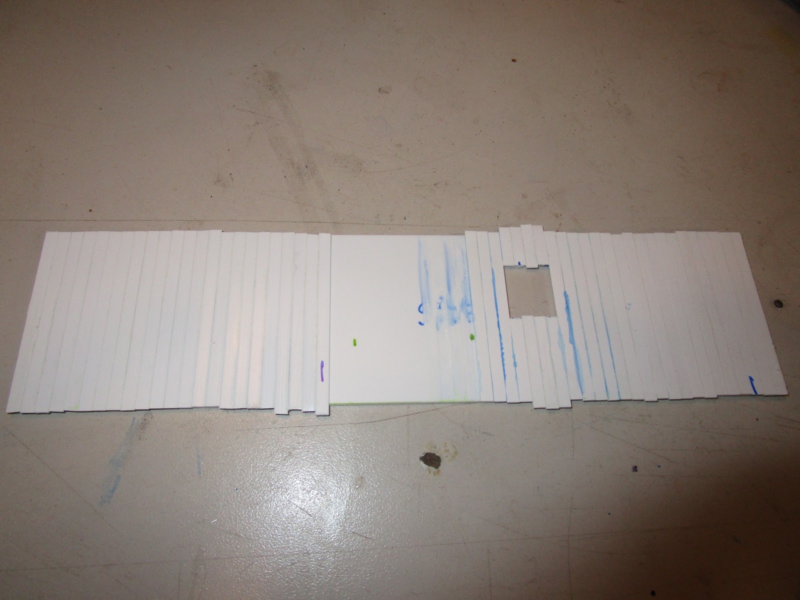
After taking the plans and photocopying them to the proper size for O scale (1:48), I then pulled out some 0.060" thick styrene and cut out a pair of sides. Some quick measurements showed where the windows were to go, and they were drilled and then "nibbled" out using a tool. I won't file them to finished dimensions until later. Next, after looking at my styrene strip collection I decided that Evergreen's # stuff (.020" thick, 0.125" wide) was as good as I was going to get. I took each "board" and ran it between some folded up sandpaper to give it a bit of wood grain, and then cut them to the height of the sides, plus a little extra just in case. Then, using my machinist's square at the end of the side with the window, I started to glue the boards down. Overhanging was okay, as they would all be trimmed at the end.

My styrene "boards" are 0.125" wide, which scales out to 6" wide. The real one might have used 4" wide boards (scales down to 0.083" wide), but if you don't include a prototypical gap between them at the joints you end up with too many boards on the sides, which doesn't look right either. When I ran out of them I had to order more online. I bought a lot more, just in case. In the meantime, I then worked on the ends of the cars. My drawing was a bit faded but I could see enough of the angles to determine the height and pitch of the roof. As for the width of the car, I deviated a little from the prototype. I widened it slightly so that I would have an even number of boards across the width without having to insert a narrow board somewhere.

All braces are straight... the left one is camera distortion!
After the four sides and ends were cut, I just pushed on. I quickly trimmed the tops and bottoms of the side I had been working on which was easily done with a knife. It leaves a pretty clean edge but one that clearly looks "homemade" and not perfectly uniform. The tops of the boards are hidden by the upper trim anyway. The four sides had bracing added at the corners and then they were glued up. Once that cured, I inserted three cross braces and also supported the corners of those braces too. At this point, the car felt pretty solid. The cross braces make it impossible to detail the interior (which might be visible through the window) but the prototype only had white boards and I might add a little bit of detail in the areas that can be seen.

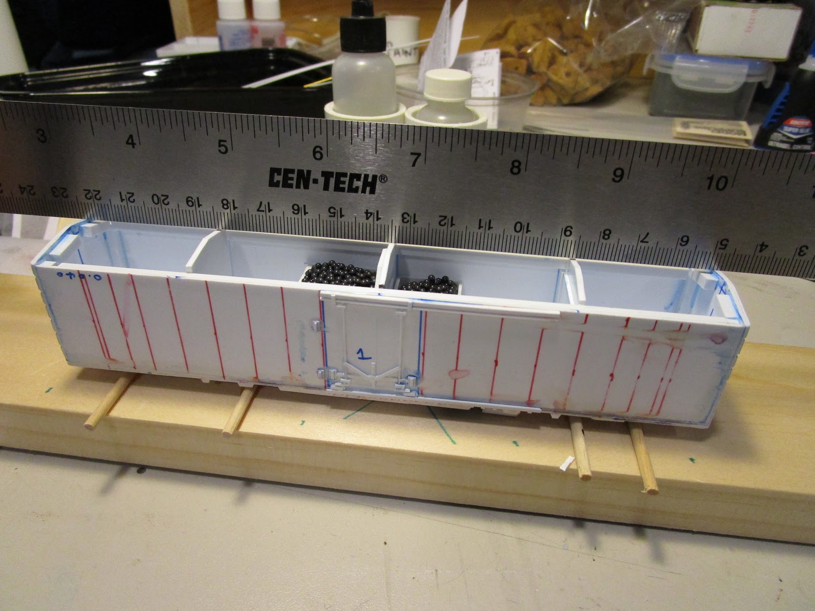
I plan to build this car with the roof attached first, which would prevent any possible future issues of getting a good roof/body joint. However, once the roof is attached there is no easy way to attach the floor attachment brackets, so I decided to add them now. It is important that they are mounted at the same height all around the car's interior- the exact height doesn't matter, and the floor can be shimmed around. But, they must be consistent. Normally I would measure up from the bottom and draw a line and hope to glue the pieces at that line, but here I took some wood dowel and set the pieces on top of that, and then applied glue. Wood was used because MEK won't stick it to plastic.

The roof will have an underlying layer of styrene. It had to be supported along the full length of I am sure it would sag, so adding styrene braces from the underside seemed the easiest method to accomplish this. The method I used was to take a flat piece of aluminum bar that I keep on my workbench (mostly as a knife cutting guide) and held it along the roof line angle with my left hand. My right had then slide some pieces of styrene into place until they were firm against the aluminum, and then I flooded the joints with MEK. Since By doing it this way, every crossbrace had its roof supports at exactly the correct angle to hold the roof.

I was able to then move back to the body, which I had to temporarily stop working on as I ran out of the styrene strips I was using The ends were done in exactly the same way except that even with my careful measurement I had a slight gap in the boards where the final one was going to be a little bit narrower than the others. Some people like to hide this board on an end, and others try and disguise it in the middle. I chose the latter, and it is only about a 1/64" narrower I doubt anyone will notice it. Once the MEK had cured, I trimmed off the tops and the bottoms. The scraps were kept, as they proved useful for when it came time to panel around the doors.

The boxcar originally had sliding doors but when the WW&F converted it to handle cold goods they replaced it with a plug door. Intentional or otherwise, it looks like the door they built was slightly larger than the space they had planned to install it so they had to cut away portions of the boards on the right and left edges to get it to fit. So, I added this detail myself. I scribed where I wanted the door lines to go and then used a metal straightedge to scribe those lines. I then used my favorite chisel blade to remove the material and clean up the corners. I then added small pieces of boards above and below the door area to make it look like the side continued around the door.

Finally, I added more boards inside the doorway openings that I had left. I grouped in bunches (left and right) to look like two doors were present, and also maintained gaps between each of the doors and the doorway openings. In my pictures you can see the blue dye run off from the marker I used. The prototype had gaps that were a little less larger but if I butted them up per the pictures you would never realize that the doors were there. I wanted this odd board spacing to be visible, so the detail had to be exaggerated a little bit. Finally, the window openings were cleaned up with a file and the car was ready for a chassis and floor to mount to.

Monday, May 25, 2020

Scratchbuilding a B&M Milk Car - Part 5 (End & Roof Details)


The ends are a collection of parts from various sources. The grab irons are formed from stainless steel wire. The brake wheel from Kadee (#2045), and the platform and support brackets are from a Details West (#2012) set. The brakewheel "chain" hanging down is from the Tichy brake casting set. White styrene rod and brackets run vertically. Some additional wire which runs from the brake wheel to the bottom finishes it off. Ladders are from Plano Model Products (#12121). The black horizontal walkway platforms at the bottom are pieces of an Athearn blue box caboose roofwalk. Precision Scale Co. air hose castings (#39117), as well as the Bowser / Cal Scale train line hoses (#275), hang out from the bottom. 

The roof had a row of rivets that went all along the perimeter. It also had ribs that went crosswise between every raised roof panel. Those I had laid out with green marker but had forgotten to install. In my haste to add rivets to everything, I mistakenly applied rows of rivets along every green line. Realizing my error, I then had to remove them all which turned out to be easy. I then installed the ribs, one side at a time until the glue cured, and then bent them over and secured the other side. I used wooden toothpicks to hold them down (so I wouldn't leave fingerprints on the soft styrene.) In a couple of minutes, the job was done.

After that, the edges of the ribs were trimmed to final length and I installed rivets around the perimeter of the roof.  I used 5/8" rivet heads, with a 2.75" spacing, to go all the way around. At this point I was piecing together parts of rows and the process itself went quickly but I had to make sure everything lined up along the length of the car. There was a bit of joy in the process as I knew the car was almost complete. It was during this time that I accidentally scrapped off some of the rivets, so after doing repairs I gave the entire car a light spray of Testors Glosscote. I was hesitant to do this as I didn't wash the body first, but with the rivet decals it is impossible to wash it anyway without them floating away. I don't know how this will affect the final finish.

The roofwalks themselves are beautiful etched metal products from Plano Model Products (#194.) There are various styles available and it was easy to find what I needed. They don't come with the support brackets, (though they are available separately), so instead I took some Evergreen #264 c-channel and sliced it into thin pieces. These were then further cut down in height and glued down the center of the car. When cured, I used a file lightly along the top to bring them all into the same plane. I then superglued the roofwalk down, using a variety of metal support brackets to hold down each joint. I could only do a couple at a time. In the future, I will invest in some super glue instant activator.

The only other detailing left to be done is to modify the trucks to add additional springing. After that, the car is off to the paint shop. Decals are on order, so it won't be long now.

Monday, May 18, 2020

Scratchbuilding a B&M Milk Car - Part 4 (Rivets & Grab Irons)

Here is what $36 of tiny rivets looks like (minus a couple)
For such a smooth looking car, there sure are a lot of rivets on it. When I built some cars in G scale I used cut-down HO scale track pins, but that wouldn't work here. Nor would embossing the styrene with a pounce wheel. I have no idea how modelers go by 20 years ago, but now there are cool resin details such as those by Archer Fine Transfers (MicroMark makes similar items) representing everything from rivets to weld seam lines to louvers. I ordered their HO scale rivet starter set #AR88087, and then their #AR88026 sets. They don't give you a lot, but between the two of them I had a lot of options. $18 for all this seemed expensive, but they were excellent quality.

The perimeter rivets installed.
I watched a handy Youtube instructional video which recommended cutting them into strips, brushing them with water, and laying them in place. I cut them into strips with scissors, held onto the end and dunked it into the water while holding it, then waited 30 seconds and applied them. It worked great. Of course, a steady hand was essential as were a good pair of eyes. I tried to use tweezers in the beginning like shown in the video but I found my finger worked better because if they slid off the sheet onto my finger I could see them and finagle them into position. If they bent over on the tweezers I had to write them off and start again.

Adding the horizontal rows of 3.25"-spaced rivets.
I first applied the horizontal row of rivets on the top and bottom of the car, working on only one side. I didn't want to bump them out of position while applying the vertical rows of rivets, so those had to wait the horizontal ones had fused to the car body. I only had about 1/3 of the car done by the end of the first night, so I had to wait a week for the full set to arrive. It took another hour to get the rest of the first side's vertical rows in place, and then they too were Microsol'ed. Then I cut and pasted bits to do the door details and other areas. It really was an enjoyable process, and aside from the fact that these things were so darn tiny it was almost fun! Certainly it was more fun than figuring out Plan B.
This side has 2.75" spacing (and 3.25" spacing on a
piece of decal for comparison)

Even with my micrometer it was impossible to measure the exact rivet spacing on the drawing for all areas. Plus, the drawings showed some that were faded out because no draftsman could really draw them to scale and have them seen. I could have tried to extrapolate that information from the few pictures I had, but come on... it is a model. And I doubt that anyone at the judging can do a better job than me at figuring it out. Thus, I used the rivets I thought worked and looked best but I might had put a 5/8" diameter one where a 7/8" should go, and the spacing of 3.75" where 3.25" would be prototypical. So sue me! Complicating matters, I didn't have enough of the 3.25" spacing for the second side so the entire thing was done with 3.75" spacing. You will never know the sides are different because they are so tiny!

The door areas were an interesting bit of cut and paste work. If you refer back to the prototype photo on my previous post you will see that what I did is a simplification of the prototype. Even with actual rivet decals, to try and cram them together into the prototype's pattern would result in a big clunky mess. In HO scale you have to draw the line somewhere, and this is where mine is. Admittedly, I am more concerned that once the car is primed and painted the rivet details will just disappear altogether. If that happens I will scream. Anyway, the picture to the right is a closeup of the car, and in real layout viewing distances it looks pretty good. It still looks naked without the grab irons though.

I am one of those "visual" people. For the handrails and grab irons, I needed to see exactly where they went in the prototype pictures to fully understand how to make them. Using pictures, and one of the photocopies of the plans that I had, I used a red pen to circle every place I had to install a handrail. I also measured them right off the plans (which were photocopied to ensure 100% reproduction) and wrote down length and height of them as needed. I also do all my measurements in millimeters, which are convenient. The 0.015" diameter stainless steel wire I use is pretty resilient to accidental bumps, but nevertheless I first drilled all the holes on all for sides and then bent up and attached the wire.

The ends not only had grab irons but also the brake wheel, the cross-over platform for the brakemen to use between the cars, and some other interesting things. I will work on them next, reserving the roof for last because once the roof is done the car can't be turned over without risk of breaking off details. Then, the corner stirrups and final underside details will go be added and the car will enter the paint shop.

And now for some boring bookkeeping. The notes below are just so I can remember what I used where in the future:

▪ Sides #1 & #2 - upper / lower horizontal rows: 5/8" diameter; 2.75" spacing.
▪ Side #1 - Vertical rows: 5/8" diameter, 3.25" spacing.
▪ Side #1 - Vertical rows at ends: 5/8" diameter, alternate center spacing.
▪ Side #2 - Vertical rows: 5/8" diameter, 2.75" spacing.
▪ Side #2 - Vertical rows at ends: 5/8" diameter, alternate center spacing.
▪ Side Doors: 5/8" diameter, alternate center spacing.
▪ Ends - Horizontal rows: 5/8" diameter, 3.25" spacing.
▪ Roof - Perimeter:  5/8" diameter, 2.75" spacing.

Thursday, May 14, 2020

BAGRS live steam locomotive (Gauge 1) - Part. 4

Boiler with new white cladding (hidden) and old yellow
insulation material that came with the kit.
This steam locomotive project had been neglected for quite some time. I reached the point in its construction (nearly the end, sadly) when four factors conspired together to shut the whole project down. First, the boiler kit came with yellow insulating material that needed to be wrapped around the boiler. Then, it had to be held in place while wooden board cladding (provided in the kit) were wrapped around it. Then, brass straps had to be placed around the boards and the whole thing secured with screws and nuts. With tape it was manageable, but after three attempts (don't ask) the yellow insulation was shreds and the bolts were superglued to the nuts. So, I pouted and let it sit for six months until I thought to call Jason Kovak at The Train Department who had replacement ceramic insulation sale that would work great. That was 6 months ago. But, by that time the garden railroading season was over so I did nothing.

Paint it all black, darken the brass, or leave it alone?
Second, I wasn't sure if I wanted to paint everything (boiler cladding, gear assembly, brackets) black or leave them wood, or perhaps chemically darken all the metal. I purchased some Brass Black which would work well but I would need to completely disassemble and clean (with lacquer thinner) the parts for the blackening agent to work properly. The all-black look would really make it appear like a Welsh quarry engine, but I wasn't sure if the paint would hold up on the brass without flaking, and that wood did look a bit nice. The decision weighed heavy on my mind and involved a bit of work, so until I figured out what I wanted to do I did nothing.

Original buffer jig on left, temporary replacement on right.
Third, I needed to mount the couplers onto the ends of the frame but I misplaced my jig that I use to mark the holes. I use this fixture on all my rolling stock, and didn't want this to be inconsistent with my other cars. I actually use two different standards for my equipment. Originally, I mounted dual-buffers on all my cars which were made from jumbo thumbtacks painted black with silver ends, and they passed as faux standard gauge cars. Then, I converted some to single center-buffer cars which is more narrow gaug-ish, and the height was based on what Roundhouse used (25mm above rail height). Being lazy, until I could find that fixture I did nothing.

Finally, around this time my new 7.25" gauge battery engine and bulkhead flatcar kits needed to be assembled and they took priority over all other train projects, so for that and the reasons above I shelved this engine. Until recently, when more time became available.

To start, I wrapped the wooden boiler cladding with blue tape to keep it together, and then used my Dremel to cut through the bolts holding the brass bands. After that, the old yellow beat-up insulation was replaced with some nice new white stuff. The process was reversed for the wood cladding and brass banding, and within five minutes the project was done. Next, having found my coupler alignment jigs whilst cleaning the basement it was another five minute job to mark the two holes, drill them out, and mount the buffers. Because there wasn't enough clearance room behind the buffers for the retaining nut, I drilled undersize and screwed the buffers tight into the wood.

Wanting to do something fun, I worked on adding a coal load to the bunker. To do this, I used my usual method of mixing real coal with two-party epoxy into a sludge, and then scooping it where I wanted it. I didn't have any "g scale" coal handy, so I took some full size Arcade & Attica Railroad coal chunks and broke them up outside in a ziplock bag with a hammer. Then, by placing them between two sturdy paper plates I could sift out it to a certain size by shifting the gap between the plates. The coal dries shiny from the epoxy which is okay, but if you sift some fine coal over the wet epoxied coal and let it all set you can then shake off the excess and have a nice, realistic matte coal pile. At least I think so.

Then I connected up the tubing and was ready to go. First, I filled the copper storage cup with two tablespoons of Sterno, and oiled everything all around. The boiler received 100 milliliters of distilled water, and the displacement lubricator got some steam cylinder oil. All told, it only took about 5 minutes to prepare. The engine was set up on blocks (that were glued to the base, just for extra security) and lit up. After 7 minutes I rotated the flywheel and after some sputtering and help with the flywheel it took off. Or, at least it ran. The cylinder exhaust shot straight forward and made a real mess of the white cardboard I had set up to prevent just such a thing! But, at least it worked on the first try.

After 13 minutes of running it slowed down and stopped. After it all cooled, I drained the boiler and found about 20 milliliters of water left, as well as a collection of black, teal, and bronze colored flakes. Residue from soldering the boiler, most likely. I also noticed two problems that I wanted to fix. First, the cylinder in-port barb was loose so I repaired it with Loctite 680 per advice here. (Even though it ran fine with it loose). The other change that was needed was to figure out how to stop that oily mess from exhausting out of the cylinder. I drilled a hole in the deck and routed some exhaust tubing down through it to the track.

I then ran the engine again, filling it up with a little less water, and it ran for about 17 minutes after coming up to temperature. I think the parts are starting to bed in and I was even more pleased with its performance. The exhaust worked well though it flooded the wood below with water. I attempted to test it on a circle of cheap tinplate Bachmann G scale track outside but it didn't like the tight radius (and, perhaps, the gauge was pinched or wide in points due to the inferior track) leading to lots of bumping and derailing... and even tipping over! But, it is fast enough to be amusing. So, success! No, it isn't a Roundhouse Lady Anne, but it is something...

Wednesday, May 13, 2020

D&H blue MOW boxcar #35622

D&H #35622 in Albany, NY (August 1984)
I bought this slide recently because there were several neat things about it. I collect D&H MOW slides from the 1980s and have a lot showing their coaches, combines, cranes, and gondolas in the "blue dip scheme", which were done in the late 1970s and by 1984 were pretty faded. But, I haven't seen this boxcar before. Note patched over numbers are a darker, more recent, blue color. It's a 40' car and I have no models of any because I have never seen a 40' car in a 1984-era picture. Yet, here is one in Albany, NY that would be quite appropriate for my layout. Interestingly, it isn't rusted very much but just faded. Usually all old boxcars from this period were rusted quite a lot from the snow and rain, but not this one. I wonder why?

Regardless, it is an interesting image and perhaps I will build a model of it someday to sit on my of my yard tracks.

Thursday, May 7, 2020

Scratchbuilding a B&M Milk Car - Part 3 (plug doors and roof)

Photo: Warren Dodgson (September 1994)
At the onset of this project there were three challenges that I knew I would face: the ends, the plug doors, and the roof. I wanted to strive for maximum scratchbuilding points (because I know other areas will be lacking and cost me points) so I reached out Bob Hamm: MMR, friend, and former director of the NMRA MMR program. He advised to scratchbuild everything so I took his advice to heart. Having built the ends which were in a previous post, I next moved on to the doors. Thankfully, again George Dutka and his friend Warren Dodgson came to the rescue and both had useful pictures of the door. I had never really considered how a plug door boxcar worked before but after studying the picture to the right it all started to make sense. There were also a bunch of interesting mini-challenges to the project. For example, much of what makes the door so neat is also practically impossible to make in HO scale without purchasing etched castings. The hinges with their bolt detail, the steel channel diagonal support pieces, the intricate upper and lower connectors between the vertical bars and the door support wheels...oy!

But, at least I was building it in HO scale, where many of those details would be lost. I couldn't locate a suitable commercial source of the c-channel for the door tracks, so I cut down some that was oversize into two pieces and then attached those L-shaped pieces at the top and bottom. Wheels were thin slices of styrene rod, joined with tiny pieces of styrene strip. By chance, I had some 0.020" rod that worked perfectly for the vertical supports. The cross braces and hinges are more slices of thin styrene. The underside of the door track is studded with tiny bits of styrene. And, the locking mechanism is a fabrication round and square styrene parts. It isn't perfect, it is the best I could do.

It was at this time that I realized I had painted myself into a corner. More accurately, into a boxcar. When I built large scale freight cars I always attached the roof to the body first, and then mated them with the frame. That way, the roof could be secured properly and also bracing underneath was a breeze. Here, I forgot the wisdom of that until it was too late. So, now I had a dilemma of trying to add a complex roof to the edges of the body without sagging or huge gaps. First, I added some intermediate bracing cut at the same pitch as the ends. I used a steel ruler to make sure that all the braces were in alignment before the glue cured. A couple of passes with a file after corrected any errors.

Then, I laid out the roof on some 0.020" thick styrene I had. From the drawings I had, I then used three colors of markers to indicate where the roof ribs and panels would get aligned. The prototype has a opposite-facing pattern and I was concerned I would mess them up part way. Green lines indicate where ribs will go. I hoped to bend the roof down the middle gentle and attach it as one piece but that didn't work and it split into two pieces, so each was was glued individually. Then, all the joints except the centerline one were filled with Testor's while modeling putty, sometimes thinned with MEK.

The roof panels had to be as close to identical as possible, and I needed a lot of them (over twenty). Luckily, I had some 0.020" thick styrene strips the exact width necessary so it was just a process of cutting each one to length and then profile. Easier said then done. My NWSL chopper came in handy for the easy first part. Then, I lined them all up against the straight edge and taped the the ends. After some measuring and marking with a pen, I had a pile of pieces that needed to be trimmed to shape. I used my favorite tool, the Xacto #18 wide chisel blade, to get the job done. It went quickly while listening to a movie, a good strategy for dealing with tedious tasks.

Then, one by one the roof panels were attached. First I lined up the wider end and glued it down, leaving the thinner end hanging in the air. I also skipped every-other panel to start so that my clumsy fingers didn't bump them while the glue was curing. After that, the thinner ends were glued by bending them down gently and holding it in position with the sides of a wooden toothpick (which prevented leaving prints in the soft styrene). One side was completed and left to cure, then the other side was done. You may notice that it is balanced on some wooden dowels, which are actually glued to the board. Those, and the markings on the board, allow me to support the car by its underside without damaging any of the delicate brake detail underneath.

I have Archer rivet decals in the mail, and there are plenty of grab irons to work on next.

Sunday, May 3, 2020

Scratchbuilding Flatcars - Part 5 (BN decals & load)

I was searching the internet a while ago for an interesting flatcar to model and decided to do a green Burlington Northern one. I came across a Tangent Scale Models advertisement for BN #610196 flatcar with "crooked lettering." My guess is that the BN stencils for the lettering were just a little too wide to fit between the flatcar stake pockets and instead of modifying the stencil the car workers just tilted it a little bit to make everything fit. It looks a bit silly, but I liked it. I also appreciated that it didn't have a lot of extra lettering on the sides. So, even though my car is based on a Thrall-built car and this was a General Steel Castings I went with it anyway. The car was decaled in much the same way as my other car, but this time I intentionally made it look like the picture which meant things weren't on the level (see what I did there?). In fact, I think I over-compensated for the slant. Oops!

Since this car looked to be in good shape I thought a stack of steel plates would be a good choice. The nearly-clean green body, the stained wooden deck boards, the rusty steel plates, the shiny black tie-down straps, and the bright white-wood stake pocket chocks and separation boards would make for a visually contrasting load. I had built some steel plate loads in the past, but the March 2016 issue of Model Railroader contained an article by M.R. Snell that jogged my memory. I cut pieces of  0.060" thick styrene into several lengths (three of one size, and a smaller one for the top for variety) and then sprayed them with flat gray primer. Then, they were dusted with Rustoleum camouflage paint to give some tooth as well as a base rust coat. Then, multiple layers of drybrushed brown and orange were added to indicate a patina of rust that was developing on the untreated "steel" plates.

For the wood which separated the steel plates to allow for forklifts to be able to move it, as well as banding to go under it, I used some more of the Mt. Albert wooden ties I had lying around. I split with with my knife into the sizes I wanted and then attached them with superglue gel to the bottom of the styrene plates. Then, piece by piece I built up the load using more wood and glue. For the banding that goes around the load, I had two choices. To mimic heavy-duty cloth strapping I have used slices of masking tape painted a dirty yellow, but for blued steel banding I used strips of black electrical tape. You can't trust the adhesive alone, so I superglued the ends under the load.

My lettering is "too" slanted. Oh well.
The deck was lightly weathered with oil paint washes, but I didn't want it to look beat up. The steel load was glued to the deck and then additional banding was added through the stake pockets. Chopped wood was installed in other stake pockets to prevent the load from shifting completely off the car due to rough handling. After that, I glued on the delicate brake wheel and shaft and the car was complete!

Friday, May 1, 2020

Then and Now: Mechanicville Yard

(November 26, 1984)
There are a couple of interesting things going on in the rail yard, and despite being about 6 months out of my modeling window I still could glean useful information. The train, for instance, is five engines long and consists of three builders: EMD, EMD, Alco, GE, and I thing EMD. What is that GE engine anyway? I wonder if it was a former D&H U23-B painted in B&M blue (unlikely), or a former blue-dip D&H engine (like #2316). Was it one of the Conrail U-boats that the D&H acquired? And why is the USDOT inspection coach in the yard? Was Guilford receiving federal grant funds some project near here? Hmmmm...


(August 14, 2012)
And here is the same yard, from about the same perspective, nearly 30 years later. While the yard was at one time nearly ripped out, a new yard was reinstalled nearby as a container terminal. That being said, though, the glory years of Mechanicville Yard are long gone. Here, instead of row after row of tracks, ballast, weeds, dirt, old switch lists, and other railroad junk are instead just now fields of green. The grass grows where once hundreds of freight cars would be sorted out into new trains and engines would get serviced. But, some things still remain. Trains led by engines of mixed builders and various railroads (that don't belong in New England!) still roll through the area, and some of them still make you wonder Hmmmm.....