Now that my benchwork is pretty much finished, I can set my sights on more enjoyable tasks such as laying roadbed and then track! I have slowly been accumulating stuff over the past year, but I am sure I will need to place another order before it is all said and done.
As has been mentioned previously, I plan to work on my NMRA Master Model Railroader certification as I build my layout. I have already earned the Model Railroad Author in 2011, and I am now working on my Model Railroad - Civil and Model Railroad - Electrical certificates. Since one focuses on trackwork (Civil) and the other the wiring (Electrical), it seems to make sense to do them together. That being said, I want to finish the electrical one first because the track one will require handlaying a bit of track, and that will slow me down.
There are a lot of requirements for each certificate listed online, though there is plenty of room to pick and choose various pieces. However, if you have a small layout like mine there are some things that necessarily might be missed. That isn't a fault of the MMR system, but it will require some creative planning on my part. One option I have is to wait several years until my layout is larger (my Watervliet section woudl have a wye, my North Albany section would have a yard) but I don't want to do that. Another possibility is to distribute everything onto the layout I have, but I don't want to compromise the vision of what I am modeling. A third option is to devote one area of my layout to the MMR requirements and cram everything on it that naturally wouldn't be elsewhere. This is what I am doing.
In addition to the paperwork that is required, including drawing up schematics and plans and such, there are some physical requirements that must be included in my layout(s). Here are the ones I selected (some were mandatory), with the numbers correlating with the NMRA requirements:
Electrical certificate
1(1): For a DCC layout, include sufficient gaps and switches to maintain polarity and troubleshoot;
1(2): One mainline passing siding;
1(3): One turntable;
1(4): A yard with a minimum of three tracks and a switching lead;
1(5): Facilities for storing at least two unused engines; and
1(6): One power supply with protective devices (short indicator / circuit breaker).
(2) Wire / demonstrate the electrical operation of a: (1) Turnout; (2) Crossing; and (3) Crossover.
(3) Wire / demonstrate the electrical operation of a: (4) Engine terminal including an electrically powered turntable, minimum of three stall tracks, and at least two blocked storage sections for parking locomotives outside of the stall area; (14) DCC decoder installation; and (23) End-Of-Train device.
Civil certificate
(2) At least 50 linear feet of track with ballast, drainage facilities, and roadbed, including examples of: a) passing siding; (b) spur; (f) simple ladder; (h) turntable; (j) super elevation; and (r) grade elevation.
Some of those things are required to be on the layout itself (red/green), while others just need to be built and demonstrated (yellow/blue). The green ones are already integrated into my Colonie Main layout design, while the red ones will be located on the one side of my layout that I don't have plans for. The yellow were built on a separate, small section because my layout doesn't include crossings or crossovers. Finally, the blue items are stand-alone things.
Even as I prepare to install the roadbed for three of the sections I need to have at least some sort of rough understanding of what will go in the last one. I plan to download some templates and play around with them to make it all fit.
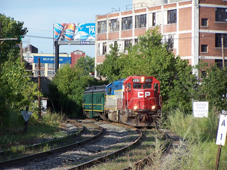
CP Executive train in Albany
Tuesday, October 31, 2017
Saturday, October 28, 2017
Finished the benchwork!
In 1492, Columbus sailed the ocean blue. Fast forward 525 years, and what did I find myself doing on Columbus Day? Finishing up my benchwork! Phew! This has been a long time coming.
 I got burned out on the benchwork a couple of months ago, mostly because I was dealing with the problem of keeping 8 separate sections (four sides, four corners) aligned on the top. But, with the lure of a three-day weekend that was absolutely free from commitments I decided to make the final push and finish it. The fourth side of the layout is only 54" long, instead of 84" like the rest. That is a 30" difference. However, it is essentially a square and the only way in or out is to either duck under the layout (not happening) or build a lift out section. Once that section is temporarily removed, there is a 30" gap to allow someone to easily walk into the layout. I didn't want to make it too narrow and tight.
I don't know what to model on the fourth side. However, I am currently working on my NMRA Master Model Railroader certificates and there are some requirements that my layout wouldn't normally have on the sections I am focusing on. So, my fourth side will essentially be crammed with whatever I need to meet the requirements. If I am awarded the certificate, I may later revise the track plan.
Building up the fourth section was pretty easy, though I was once again startled to see how out-of-square the frame would turn out if I built assembled the 1x4" lumber first and and then tried to attach the plywood. So, I built the outside box, then secured the plywood on top, and only then added the cross braces. There are no diagonal corner braces added yet, because I plan to add a large shelf beneath the layout. This will be used to hold the DCC system, any other power or sound system components, etc.
 The last corner section is also different from the others because I took a slice off the outside corner to allow easier access to the laundry area. This was my wife's idea, but it was a good one. The corner sections are essentially just filler/temporary areas anyway. I couldn't build it per my normal drawings so instead I built it bit by bit, cutting one or two pieces of wood at a time and then gluing them up. This was a bit tedious, but it meant that every piece was cut exactly to the proper length and angle. The interior bracing was made from a 2x4", which is a bit overkill but I ran out of 1x4" lumber. The plywood top was a cut and paste job, with the gap braced on the underside and then filled with latex caulk, though harder Liquid Nails would have been better.
But that was several weeks ago. Why the delay in posting to this blog?
 I was having issues with the four wires that pass between each benchwork section. The problem was that the wooden blocks with the 10-24 bolts were too short and located too close to the ends. The wires had to make a sharp 90-degree bend to attach to the bolts, and there was no place for any slack in the wire to go. Plus, some of the bolts I used were spinning in their holes because I didn't use carriage bolts. So, I made taller ones and located them farther out from the ends. I cut down the old bolts using a Dremel and that took forever. To prevent cuts on the sharp ends, I put a dab of caulk on each one. I also shifted some of the wooden 1x2" lumber screwed to the L-girders to allow for easier access to the wingnuts.
 Also, I have been having trouble leveling the benchwork because the ends of the 5/16" carriage bolts are hard to reach below the legs. Plus, with the weight of the layout bearing down on them they are tough to turn by hand, and a wrench is clumsy. So, I fell back upon an idea that I came across on the Model Railroader forums by someone named "Batman" (if that is his real name) which used hockey pucks. It was worth a try, so I ordered a bunch of hockey pucks on EBay for $1 each. I drilled and countersunk the bolts into them, and put a nut and washer on top heavy tightened down to prevent spinning. They work great!
 Unfortunately, while installing them into the legs of the benchwork the T-nuts kept falling out. The T-nuts only have three little prongs that dig into the wood, and they just weren't up to the task. I honestly don't know how other model railroaders have never had this problem, but I needed a plan B. I saw some T-nuts with holes drilled in them for three tiny screws, but that didn't look too solid. So, instead I bought some furniture leg brackets online. When they arrived, I was surprised to discover that the thread didn't go all the way through them. So, I took them to my friend's house and he quickly used a power tapping head in a drill press to finish the job. The threaded brackets were 2" square, which was a little bit larger than the layout legs. So, I fabricated some simple wooden "L" shapes which were predrilled and then glued and screwed to the benchwork legs.
 I could now level the layout. Working on one section at a time, I carefully jacked up the layout a little bit with my Toyota Corolla car jack to give me enough clearance. Because it wasn't entirely stable, my wife assisted by holding the "t" wooden brace together while I spun the jack. I first removed any remaining T-nuts that were still in the wood by wiggling the bolt. Then, I roughly set all of the hockey pucks to the same level by spinning them. They were then glued and screwed to the bottom of the leg, making sure they were perpendicular to the legs. I then lowered the car jack until the layout was at the desired height, and un-threaded the hockey pucks until they firmly resisted against the floor. I was amazed at how simple a process this turned out to be. To adjust the layout, I found it best to raise/lower it with the jack instead of just screwing in/out the hockey pucks. Otherwise, too much weight would be put on the hockey pucks and they might strip out. The next day, I worked on another section, adjusting it to be level with the first one. And so on, until the project was finished. It set me back a couple of weeks and about $50 for the metal brackets, pucks, and lumber, but I am really happy with how it turned out.
In the end, the benchwork cost me about $650 total. I could have probably saved $50 with better planning, and another $50 if I had a truck large enough to allow me to get my lumber in longer lengths. Would I do it again? Probably not. It seems like it should have been easy (measure, cut, glue, screw) but it wasn't. At least not for me. Prefabricated benchwork would have cost me a lot more, but it might have been better. Oh well.
Finally, I can now work on more interesting things like roadbed, painting the plywood, laying track, wiring, etc...
Thursday, October 19, 2017
D&H whimsical models
I was scrolling through Ebay recently as I usually do, looking for any D&H items that might be of interest to me, when I saw some models that just had to make me shake my head. There are times when a manufacturer takes a model and slaps any road name on it to try and sell it to the unsuspecting public (or perhaps someone who knows it is wrong but doesn't care), and I guess I understand that. Examples that come to mind are steam locomotives, with any old road name listed on the tender, and boxcars. The D&H didn't roster any PB-1 engines but Athearn still did one in blue and silver.
 Along those lines, when Riverossi released its E8 engines in both A and B units they painted some in the sharp blue and silver scheme. They look great, and remind me of the PAs (as I am sure Riverossi hoped) but they are completely fanciful. Not only did they get to sell the engines, but they also released passenger cars to go with them! In a move that was surely done with forethought, they numbered the A units "15", which is smart because the PA units were numbered 16-19. So, no conflict there. Still, I don't think any will be joining my roster anytime soon.

 But, there are some real head-scratching models out there too. For example, D&H cabooses. Most were painted red, though some bay window cabooses were painted yellow in 1968 when delivered. They lasted only a couple of years before they were repainted red. Also, Guilford had some cabooses that were painted into orange in the 1980s and 1990s. However, Like-Like must have anticipated this when they released a model of a "North Eastern" caboose, which the D&H actually had, but instead of painting them red they used orange. Then, they used a font that screams "1940s" and varied the location of the shield (centered, and off-centered). I think they were produced before Guilford, so the choice of orange instead of red doesn't make sense.
 Like-Like then decided to paint cabooses to match the engines it was also selling, EMD Geeps in the "Lightning stripe" scheme. But, the D&H never had any cabooses painted in gray and blue! This time, they actually used a font style that is somewhat plausible and picked a number that fits in the range of D&H cabooses. The large shield is a nice touch, though too large. I must say the engine and caboose sold together in the combination box looks nice, even if it is unrealistic. Why again didn't Life-Like just paint the cabooses red?
 Not to be outdone, Lionel too painted up a bay window caboose to match their U33C engines which were done in a very dark rendition of the Lightning stripe scheme. I can't say I like it, and wouldn't recognize it as a D&H caboose were it not for the circle emblem on the right. But, Lionel has been doing this sort of stuff for ages.
 Then there is Bachmann, that went with red in the wrong way. They decided to release some D&H hoppers in red and have been doing so for decades. Even my first train set in the mid-1980s had one. I remember loading it with sand or some other scenery material and gluing it in place. Unfortunately, the D&H never actually owned bright red coal hoppers. In fact, that idea is absurd, as they would get dirty quickly. I don't know which came first, but Bachmann actually released two different hopper cars in red with D&H markings. One featured yellow letting and a bright shield, the other was red with white lettering.
 However, at least as it regards the yellow lettering and the shield, the D&H did roster some covered hoppers that were painted this way. I think they look really sharp, and have a couple of models myself. Perhaps someone at Bachmann thought that the paint scheme would translate well. I think if I want to run unit D&H coal trains I will stick to the black or brown hopper cars! However, for a train running under a Christmas tree it would look pretty festive.
What is the point of this rambling? Well, it shows me how far I have come in terms of the D&H. Just ten years ago, I couldn't have told you anything about the railroad except for the Lightning stripe scheme. Had you offered me a PB or E8 engine, I might have bought it. (A couple of years ago I bought an O gauge FM Trainmaster in D&H's Lightning stripe scheme, and seriously considered buying a GP7 even though I knew they were fakes... so rules are meant to be broken). I only learned last year about the history of the yellow cabooses. I doubt I would have fallen for the orange or gray ones, but who knows? I shouldn't be too critical of the manufacturers. When it comes to train set equipment, anything that will sell will probably be made. But, it is fun to look back and wonder at some of their decisions.
 That notwithstanding, there is a line that must be drawn and to me seeing a steam locomotive painted Conrail blue with a "can opener" on the tender clearly crosses that line. Note: here is a tongue in cheek take at a Conrail "Rocket" 2-2-0 engine (scroll down the link to see it) which is pretty amusing!
 Along those lines, when Riverossi released its E8 engines in both A and B units they painted some in the sharp blue and silver scheme. They look great, and remind me of the PAs (as I am sure Riverossi hoped) but they are completely fanciful. Not only did they get to sell the engines, but they also released passenger cars to go with them! In a move that was surely done with forethought, they numbered the A units "15", which is smart because the PA units were numbered 16-19. So, no conflict there. Still, I don't think any will be joining my roster anytime soon.
 But, there are some real head-scratching models out there too. For example, D&H cabooses. Most were painted red, though some bay window cabooses were painted yellow in 1968 when delivered. They lasted only a couple of years before they were repainted red. Also, Guilford had some cabooses that were painted into orange in the 1980s and 1990s. However, Like-Like must have anticipated this when they released a model of a "North Eastern" caboose, which the D&H actually had, but instead of painting them red they used orange. Then, they used a font that screams "1940s" and varied the location of the shield (centered, and off-centered). I think they were produced before Guilford, so the choice of orange instead of red doesn't make sense.
 Like-Like then decided to paint cabooses to match the engines it was also selling, EMD Geeps in the "Lightning stripe" scheme. But, the D&H never had any cabooses painted in gray and blue! This time, they actually used a font style that is somewhat plausible and picked a number that fits in the range of D&H cabooses. The large shield is a nice touch, though too large. I must say the engine and caboose sold together in the combination box looks nice, even if it is unrealistic. Why again didn't Life-Like just paint the cabooses red?
 Not to be outdone, Lionel too painted up a bay window caboose to match their U33C engines which were done in a very dark rendition of the Lightning stripe scheme. I can't say I like it, and wouldn't recognize it as a D&H caboose were it not for the circle emblem on the right. But, Lionel has been doing this sort of stuff for ages.
 Then there is Bachmann, that went with red in the wrong way. They decided to release some D&H hoppers in red and have been doing so for decades. Even my first train set in the mid-1980s had one. I remember loading it with sand or some other scenery material and gluing it in place. Unfortunately, the D&H never actually owned bright red coal hoppers. In fact, that idea is absurd, as they would get dirty quickly. I don't know which came first, but Bachmann actually released two different hopper cars in red with D&H markings. One featured yellow letting and a bright shield, the other was red with white lettering.
 However, at least as it regards the yellow lettering and the shield, the D&H did roster some covered hoppers that were painted this way. I think they look really sharp, and have a couple of models myself. Perhaps someone at Bachmann thought that the paint scheme would translate well. I think if I want to run unit D&H coal trains I will stick to the black or brown hopper cars! However, for a train running under a Christmas tree it would look pretty festive.
What is the point of this rambling? Well, it shows me how far I have come in terms of the D&H. Just ten years ago, I couldn't have told you anything about the railroad except for the Lightning stripe scheme. Had you offered me a PB or E8 engine, I might have bought it. (A couple of years ago I bought an O gauge FM Trainmaster in D&H's Lightning stripe scheme, and seriously considered buying a GP7 even though I knew they were fakes... so rules are meant to be broken). I only learned last year about the history of the yellow cabooses. I doubt I would have fallen for the orange or gray ones, but who knows? I shouldn't be too critical of the manufacturers. When it comes to train set equipment, anything that will sell will probably be made. But, it is fun to look back and wonder at some of their decisions.
 That notwithstanding, there is a line that must be drawn and to me seeing a steam locomotive painted Conrail blue with a "can opener" on the tender clearly crosses that line. Note: here is a tongue in cheek take at a Conrail "Rocket" 2-2-0 engine (scroll down the link to see it) which is pretty amusing!
Subscribe to:
Posts (Atom)