CP Executive train in Albany

CP Executive train in Albany

Monday, April 27, 2020

Scratchbuilding Flatcars - Part 4 (Conrail decals & load)


I mentioned it in my last flatcar post, but one of my two cars will be Conrail #716019 based on this picture I found online. The prototype isn't the same: my car is based on a Thrall built flatcar and the picture is of something else. But, I liked its beat up appearance and it seemed as good as any. Once again Ricky at Modern Rail Decals came through for me with some decal sets custom made for my cars. They went on super easy and were strong enough for someone with my "delicate touch" to hamfist into position. After the car was done up, all of the decals were sealed with Dullcote and it was ready for a load and some weathering.

Photo by Jonathan Fischer, used with permission
I knew I wanted to try and get as many merit points as I could, so adding a scratchbuilt load seemed natural. The Conrail flatcar was supposed to represent a beat up car so carrying a brand new load just wouldn't make much sense. Something like MOW equipment, wheels, scrap rail, or ties seemed more appropriate. While searching the internet, I found a fantastic picture of an Alaska Railroad flatcar with a load of used railroad ties. The ties are just mounded on the car, and some look like they are ready to tumble off! Additionally, the "end restraints" look to be nothing more than steel square tubing and chain. All of it would require scratchbuilding. The kicker was that I had a huge bag of HO scale wooden ties on my shelf with no purpose.

Lots of ties (vertical) with horizontal tape masking
everywhere except where I want the rust pain to show.
The ties, from Mt. Albert Scale Lumber, were purchased through Fast Tracks... the same company that makes those neat track jigs. I think I bought them while laying track to slide under rail joiners, but discovered that they are much thicker than plastic flextrack ties (they scaled out to 7" x 9" x 8.5' which is correct for many railroad ties) and were more work to sand down than the plastic ones. They are only sold in bags of 1000, so I had about 998 left! They were stained in a very dark ink/alcohol wash for 24 hours and then left to dry. The photo showed that the ties were definitely used because there were rust stains where either the rail itself or tie plates had been. This looked to be a fun detail to replicate, so I used some scrap balsa wood and poster board to make a "tie plate weathering jig."

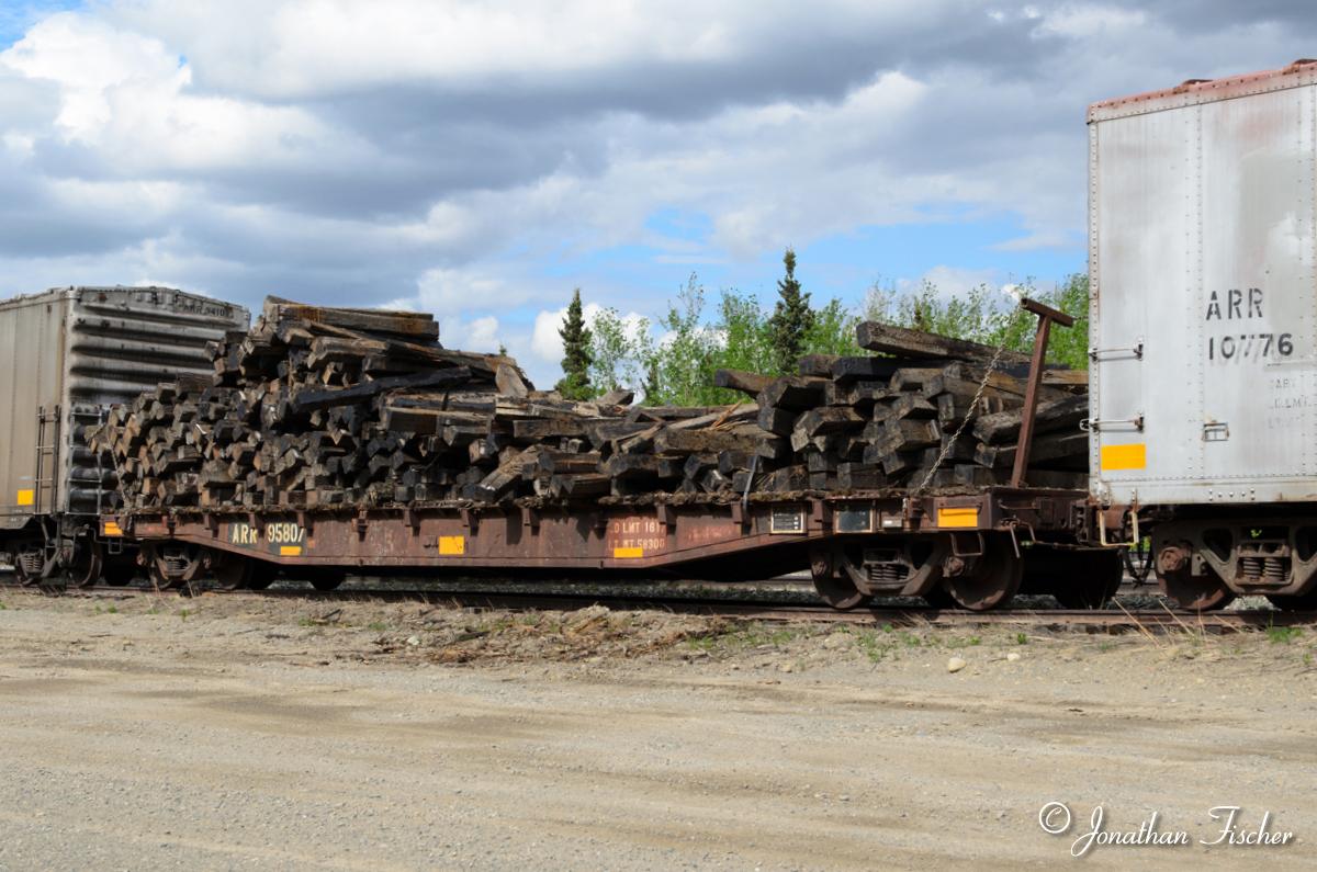
The load was built up on a base of clear 0.010" styrene, which is thin and yet allows the load to be removed. The first layer of ties were superglued to the base and subsequent layers were built up with white glue. I placed each tie by hand. Finally, a light sprinkling of real dirt, ballast, and green foam were applied and then shaken off. I probably could have used another 100 or so ties but I threw out the stain first so I can't make more. I also fabricated some support brackets similar to the prototype picture using C-channel and square strip styrene. The flatcar deck was then heavily weathered with additional oil stains.

Ignore the diagonal shading under the stake pockets!
Finally, everything was put together. The Kadee couplers and Accurail trucks were attached with 2-56 screws into holes I had drilled before the wood decking went on. I replaced the terrible looking wire "glad hands" at the ends with Precision Scale Co. castings, which look much better. The brake wheel and shaft were installed on the end of the car. The load was secured to the deck with thick superglue gel, and then the tie retraining brackets were strung up with some 45 links-per-inch chain I bought from Crescent Locomotive Works and secured with superglue into the stake pockets. Everything was given a final coat of Dullcote and then I was able to call the car finished.

Friday, April 24, 2020

Weathering British Rail coaches


Since "The Great British Train Show" in Toronto has unfortunately but necessarily been cancelled, I am posting about a replacement British-themed project I was working recently. At the December "Great Train Extravaganza" show in Albany I picked up four British Railway OO gauge coaches for $6 each. They are old Lima brand models and the detailing is a bit dated. I remember seeing Lima advertisements in Model Railroader in the late 1980s and early 1990s for their British and especially African Railway trains. Even though the coaches' detailing is a bit crude, I had some money in my pocket to burn and so these four cars came home with me.

After doing a little digging online, I found out that they were models of cars that were from the late 1960s and early 1970s in Britain. Having only a few other British models in my collection, and with nothing that matched, I was essentially starting from scratch. I took them apart (not very easy as they had lots of internal tabs... which I cut or ground away to prevent future problems) and then surveyed what I had. They came with basic interior moldings, and the roof also contains clear glass sides which slip into the car's four walls to provide the window glass. I marked the inside of each car, its matching roof, and interior to allow me to get them back together in their proper configuration later.

The wheels were metal, which was nice, but the flanges were huge. I turned down one set on my belt sander and decided it was too much work to do the rest. Intermountain 36" metal wheels were too small for these cars (which are 1:76 scale, and the prototype wheels are larger than 36" anyway, meaning I needed much larger wheelsets). I planned to get them at the G.B.T.S. but its cancellation forced me to Plan B which was a company in the U.K. called Peter's Spares, who also have a handy EBay store. They fit perfectly in three sets of trucks, but in one set they were tight. Dimension wise they checked out okay, so two of my trucks must be slightly warped.

The car trucks were sprayed flat black and then drybrushed with brown acrylic paint. This goes on bright but it dries to a nice dull color that looks like both dirt and rust. The wheelsets were also given this same color on all surfaces. Then, I removed the roof/window pieces and lightly drybrushed the sides of the coaches with the same color brown. The black ends were given a heavier treatment, especially around the diaphragm and buffers. After that, I applied a black oil paint wash to the sides. The roofs on all the coaches were spray painted with a dark gray color and then given an alcohol & ink wash. Then, everything was Dullcoted.

The interiors need to be repainted too, as that yellow is really garish. The white bathroom windows (I think?) are scratched up and also could use a repaint. Then, I will add some figures and that will be that. Now, I just need a diesel to pull them.

Tuesday, April 21, 2020

Amtrak Heritage Unit #712


Amtrak has a soft spot in my heart. I have fond memories of my parents and grandparents bringing me to the train station. And, I think that the Phase III scheme with its equal spacing of the red, white and blue stripes always looked the best. But, in 1994 the new Phase IV scheme with dark blue and white pinstripes was unveiled and that slowly marked the end of the Phase III scheme. So, imagine my delight when Amtrak joined the Heritage Unit bandwagon. In 2016 it was announced that all locomotives on the "Empire State Express" service would be repainted in a modified Phase III scheme. I had seen a couple but never got a picture of one until recently when I went trainspotting in Amsterdam, NY. This shot shows #712 slowing for the station only a couple hundred yards ahead. While not the best shot, I will take it! Now I can cross it off the bucket list.

Sunday, April 19, 2020

A Suspended Ceiling at last!

Still need more lights on the closer side of the layout
One of my dreams came true this past week as I finally had a suspended ceiling installed in my basement. I had been planning this since we moved in and obtained several quotes, but no contractor that I talked to really understood what I was trying to do. One wanted to sell me a full basement conversion, another couple heard what I wanted and decided the job was too small for their troubles. One guy really bought in that I just wanted a simple, clean ceiling and took the time to explore the problems in my basement that might cause him some trouble. We agreed to only put it up a ceiling in three-quarters of the basement, as the other quarter had too many low-hanging utility pipes.

The basement after 2 solid days of painting it all blue.
After coming to terms last fall, I had to wait until recently to get it done because of scheduling, funding, and other things. But, with the recent pandemic going on I reached out to him to see if he wanted to move up the job. Since I was home all day anyway, I didn't need to take off time for it. He readily agreed, and so last week he came over with his crew to put it up. There were of course problems, like not having a square wall in the place, plus the stores were all sold out of commercial grade ceiling tiles. But, we got through it. And he seemed somewhat impressed by my train layout (as much as is completed so far.) I could hear him talking with the other guys about his grandfather's layout.

The basement on closing day. I inspected here first.
The lights are great. The contractor selected recessed LED lights which are great for a couple of reasons. First, they are cheap and will last a long time (and supposedly save the earth because they use less energy). Second, they are adjustable in terms of what Kelvin level (light color) you want. And, LEDs won't fade your scenery like other types of lights. The brand we used is Utiilitech (#1500765) and the colors are 2700k, 3000k, 4000k, 5000k, and 6500k. After some experimentation and a lot of previous research online, I went with 3000k. They are nice and warm and sunny, and any more into the 4000k range looked too blue to me. Having blue walls might have amplified that. I think 3500k would be perfect, but oh well.

The basement during the Open House.
I am glad I did the ceiling now and held off on the scenery. Boy, it was really filthy up there and even after covering up the layout with protective paper and such I still had to do a lot of vacuuming. For those who decide to do it after a layout is installed I say that they are crazy! And speaking of crazy, what is with the weird pictures? The first is obviously how the layout looks now. It still needs things like backdrops, scenery, and a proper fascia. They will all come in time, now that I have the ceiling installed.

Thursday, April 16, 2020

Scratchbuilding Flatcars - Part 3 (painting & wood decking)

I don't own an airbrush, so to paint the cars I needed to use rattle cans. I also wanted to avoid the paint found at the big box stores as it usually comes out much too thick, and the nozzles are terrible (except for the Krylon ones). One flatcar was going to be done in Burlington Northern green, and the other in Conrail brown. Both choices are throwbacks to two railroads that I have always been fascinated with. Had a hobby store been open, I could have wandered in and easily picked out the right cans of spray paint. But, they aren't, so I relied on a non-local (80 minutes round trip) hobby store to choose them for me and leave them hidden outside for me to pick up. The Tamiya paint he chose (TS-1 "Red Brown and TS-35 "Park Green" are pretty close).

After using primer on the underside to hide all my ink markings, I painted the cars with multiple light coats. I didn't bother to heavily paint the top deck side because it would be hidden with board. But, I couldn't help but notice that on the underside even after priming and painting the cars some of my Sharpie markings were still visible. They should disappear during the weathering treatments I plan to apply, but it is still a bit concerning. Also, at this time I noticed that the thin styrene deck had warped so I sanded it flat. As you can see, some areas were worse than others. I then resprayed the tops, even though it will all be hidden under the decking.

The flatcars looked pretty naked without their decking. For these cars though I wanted to use real wood. I looked into purchasing HO scale 2x12" boards from suppliers and cutting them down to length myself but then I ran into an EBay posting from "Crescent Locomotive Works" who sells laser cut wooden boards in various lengths. He didn't have the side I needed off hand, but we worked out a deal for him to custom cut them for me. It cost only about $7 for enough boards for two cars, and each end cut is perfectly square. That is a bargain to me. They were stained in a "dark" ink wash (1 pint of rubbing alcohol, 2 teaspoons ink) using a recipe I likely stole from Dave Frary.

The boards were divided into five batches and added to the alcohol at staggered times, such that the first group was in the stain for 12 hours and the last batch was only in for 4 hours. Then they were all left to dry overnight on some paper. They really looked pretty similar in color and I was a bit disappointed. On my shelf is a can of dark Minwax stain left over from my handlaying days, so I considered pulling it out to further color the ties. But, in the end I just used what I had made. As you can see from the car, there actually is a bit of a difference in the color of the wood. Not so much as to be obnoxious, but enough that it looks pretty realistic.

As mentioned above, the flatcar tops were not perfectly flat. In fact, on the Conrail model especially it was nothing close to flat. That thin styrene buckled quite a bit. Since I am modeling the Conrail car as an older car in MOW service a bit of ruff and tumble is a good thing. Perhaps planned? And, I wanted the deck boards to be a bit more worn down and rough than those on the BN car. Even still, I had trouble getting the boards to come close to lying flat on the deck and had to result to clamps. So, the procedure went like this: lay down a bead of Loctite Gel Superglue, apply two boards, and clamp with clothespins for 20 minutes. Working from home, it was easy. Had I only had evenings to do it, though, it would have been utterly frustrating.

Also, I had to notch the boards around the stake pockets. It wasn't terrible difficult, especially with a chisel-blade knife, but more than once I laid down the superglue only to discover I had forgotten to notch the boards. It took a few minutes for the glue to set, so I could easily pull the board up and cut away the offending areas. The Conrail flatcar will need a bit more weathering of everything, including the deck, and I might try and scratch up the wood a bit to represent a dragged load. But, in the end, I am really pleased with how the cars came out.

Sunday, April 12, 2020

Scratchbuilding a B&M Milk Car - Part 2 (car body & brakes)

I think that it is important to learn new skills and grow as a modeler. With each new freight car I am scratchbuilding I am trying to develop new techniques and push myself. With my O scale caboose, it was just taking the first steps on something small and simple. The HO scale flatcars had more complicated frame and brake gear components and the parts were smaller. Here, there are three distinct areas that are going to be difficult to replicate and thus pose interesting challenges. First, the plug doors on the sides. Second, the ends. And finally, the roof. And despite there being commercial castings for all three elements I decided I would scratchbuild each.

The body is a simple box made from 0.040" thick styrene. After going in on a group purchase with some friends, I also have a large amount of thicker styrene sheets in my inventory but this seemed a good choice for the car. Following the plan, I laid out the sides and ends. It is also important at this phase to compare my measurements to the floor I already built, because if it was over or undersize then some adjustments might need to be made. Thankfully, I will still spot on. The corners of the cars were braced with styrene rod, as was the bottom. I left off top bracing at this time because I still need to figure out how I am going to build and attach the roof and I don't want anything to limit my options yet.

I should point out at this time that I didn't plan to start working on the body. I wanted to push forward with the frame and add the brake details and other things first. However, despite my best efforts to brace the inside of the frame to my dismay I discovered that it was still bowing too. I don't understand this phenomenon at all, but I couldn't let the floor continue to bend. So, I jumped ahead with building the carbody so that it would act as a straightener for the frame. After holding it securely all over and letting the joints fully cure, I also made sure to go ahead and add three interior bracing walls to support the middle of the sides of the car.

At this time I took measurements and I laid out all of the vertical lines which would later receive rivets, most likely via decals. There will be a lot of rivets to add! I also marked out the doors. A small machinist's square was pretty helpful. I need some better pictures of the door and sliding doorway hardware and guides before I can build them, so I am deferring them to later. Again, it would have been awesome had the museum still had this car out for display as I could have taken a million pictures and perhaps some measurements. As it is, there is only one known car to exist and as I later discovered even the brass models got some details wrong.

Picture by George Dutka (2015)
The ends came next. From some research I did I discovered that the ends are the "Dreadnaught" style ends. The term was supposed to conjure up images of Battleships and such, with the implication that the ends of the cars would as tough and strong as those ships. Maybe. Anyway, there are various styles of Dreadnaught ends (check out the Oct. 2014 Model Railroad Hobbyist Magazine for an excellent article) and my car had ends similar to those found on express reefer cars. While referring to the brass models available I noticed that they weren't correct. They showed partial ribs on the ends between the main ribs where there should actually be just straight lines, which is prototypical for the double-door series car but not the single door cars. However, George Dutka came to the rescue and sent me some pictures which he also kindly allowed me to repost here... thanks George! Some interesting points are the rounded over corners, the grooves in the corners which form a squiggly pattern (technical term), and the intermediate ribs or bulges or whatever they are in between the six full size ribs. Modeling it will be a challenge.

I initially considered purchasing commercial end castings and modifying them to match the prototype but was counseled by another M.M.R. that this would not be a good decision. It would be better to make them myself. The ends started off as pieces of 0.020" styrene. I didn't want to fabricate the ends directly on the car because if I messed up I would need to shave and sand down the carbody itself. Instead, I wanted something I could glue on later once I had them how I wanted them. I laid out the locations of the horizontal ribs and also the prominent row of rivets. Again, I used a square to make sure everything lined up correctly.

Each of the ribs is a piece of styrene that I essentially divided into thirds lengthwise. Then, the outer thirds were chopped with my chisel blade until the profile was of a really squat octagon. The ends don't actually come to a point but they are very close thereto. Then, each piece was glued onto the car end pieces with MEK. After the solvent had evaporated and cured, I looked over what I had done and was pretty pleased with the results. At this moment, I pushed all the chips to the center of the table and went all in. I was concerned that the ends might warp, so I glued the ends to the carbody structure and made sure that it was securely attached.

Once that was done, I took a large flat file and removed material from all five ribs so that they tapered down in thickness as it reached the edge of the car. I did this with both ends and then I took small needle files and went between the ribs horizontally to knock down the sharp edges. My goal was to smooth over the pieces enough to look like a stamping. Finally, I took my files and rounded over and then notched the corners to match prototype pictures. Then, I added smaller pieces of styrene 0.020" rod between the ribs, as well as a plate on the bottom. The dust and chips were cleared and I flooded everything with MEK with a brush and that actually melted and fused it all together.

Unlike my O scale caboose which might just sit on a display shelf, I planned to run this car on my layout from time to time (even though by 1984 it was likely falling apart in real life) so I wanted to put weight inside it where it would be hidden. I build a couple of boxes from some scrap styrene I had to hold lead shot. I weighed 3 ounces of the stuff and mixed it up with some two-ton epoxy (the longer it takes to set, the stronger it is and the more I like it) and then poured it into the boxes. They were secured to the braces that run along the floor but don't touch the floor or the walls directly. That way, if I have to drill holes for wires or grabs or whatever I won't have to drill through epoxy/lead.

The above was spread out over a couple of days and by then the the Tichy brake castings set (#3013) arrived. Only a few of the pieces matched what I needed, but it gave me a start. The rest, including the tanks and brackets, were fabricated from styrene tube and channel stock. The connecting lines were bent from 0.015" brass and 0.020" styrene rod. I did the best I could based on the drawing, but the good thing is that once it is all painted black it will likely disappear in the shadows. I also built up the truck bolster area to provided greater clearance for the trucks to rotate. I may need to adjust the coupler box height as well.

From this point on, the car is a bit fragile and difficult to put right-side up. I may build a simple cradle to hold it. Next step: either the roof or the doors.

Friday, April 10, 2020

Ground throw "indicators"

I love Caboose Industries ground throws but there is one crucial problem when you mount them at the edge of the layout: you can't easily see if the switch is set to the "normal" position. I am generally the only one who operates my layout and I always leave the switches set for the main line, but a mistake will cause a train to take a 4 foot drop to the floor. I needed an easy way to determine the position of the switch at a glance. Some people paint the handles with red, yellow, and green paint but I think this looks horrible, as the paint inevitably flakes and it draws attention to the out-of-scale ground throws. At the edge of the layout it isn't be so bad, except that you would need to walk over to the ground throw to see it. I wanted to be able to see from the middle of the layout area how they all were. LEDs or other lights were an option, but I am lazy (I did just remove all the Tortoise switch machines, after all).

I saw online a gentleman had glued beads to the handle of the ground throw to represent marker lights. These beads kept the handle from dropping all the way down to the layout, which apparently was then harder to grab. I didn't like how they looked but the bead idea got me thinking. So, I purchased some cheap beads online (my local hobby store didn't have a good assortment... I guess kids don't play with beads anymore), and nailed them to the layout. And, for the record, this (like all of my projects) turned out to be a Benny special. The first set of beads I ordered were 4mm (too small) and the next set were were 12mm (too large). I also ordered some 8mm cubed beads (never tried them) but finally ordered 6mm beads and they were perfect.

A couple of things to keep in mind. First, once all your scenery is done with the beads might be visually lost in the grand scheme of things. I might keep a little area around each ground throw clear of grass and weeds to prevent this. Second, any beads taller than 6mm might prevent the handle of the ground throw from rotating all the way if you place the beads directly under the handle. Third, beads smaller than 6mm have smaller diameter holes drilled through them which require smaller pins to secure them or they will shatter. However, I am pleased with how this turned out. In fact, when I had a contractor over recently he saw my layout and pointed out that he really liked the ground throws. So there.

Tuesday, April 7, 2020

Scratchbuilding a B&M Milk Car - Part 1 (frame)

#1920 (August 20, 2017)
As part of the MMR program I am currently scratchbuilding some flatcars. But, I am waiting for the decals so I thought I would start on another. Car #4 will be something special. While scrolling through EBay one day looking at B&M slides I saw several for some attractive black boxcars with the intertwined "B" and "M" logo. Further digging revealed they weren't actually boxcars but instead were reefers, and they were designed for milk service and have have heating pipework to run in passenger trains. I liked the clean lines of the cars, the simple paint scheme, the uniqueness of the cars, and the fact that two of them still exist. I knew I wanted to build one.

Built by General American Tank Corporation (GATX), they likely were the last true milk cars ever delivered to an American railroad. Cars #1900-1914 had four plug doors (2 per side) and were built in January 1958. They were insulated and had mechanical refrigeration and were designed to handle bottles of milk. Cars #1915-1934 had two plug doors (1 per side) and were built in December 1957. They were insulated only and were designed for handling milk cans which were covered with crushed ice. Some were used for moving milk from the Bellows Falls Creamery in Vermont to Boston and lasted in service through 1965, when they were converted to company storage cars.

#1920 at RMoNE (May 2018)
Two cars survive today: #1910 (a 4-door car) and #1920 (a 2-door car). They were purchased by the Railroad Museum of New England in 1989 and car #1920 was restored in 1992. Car #1910 still requires restoration. For some additional information on these cars, check out George Dutka's "White River Division" blog which also contains some pictures of them at the end of their working lives. I even planned a trip to the Railroad Museum in New England in 2018 to see this car and photograph it, as it was supposedly on display. However, at the time we were there the exhibits had changed and the car had been moved to an inaccessible place. So, the best I could do was take this picture as we rolled by on the train.

There are several additional sources of information for building models of these cars. Railroad Model Craftsman magazine ran a series of articles in 1986 (February, March, and May) about milk trains in general and the February issue contained several plans including those for both 2-door and 4-door B&M cars. The Boston & Maine Railroad Historical Society's newsletter also contain several articles in their "modeler's notes" section:
- #80 (Sept. 2002) – by Bruce Bowden – “B&M 1900 Series Milk Cars”
- #96 (May 2005) – by Bruce Bowden – “Modeling B&M 1900 Series Milk Cars”
- #101 (March 2006) – by William Keay – “Milk Cars Used on the B&M”
- #103 (July 2006) – by Bruce Bowden – “Modeling B&M 1900-1914 Four Door Milk Cars”

Athearn HO scale #RND84640
For those who don't want to completely scratchbuild the car, there are several options. Brass models in HO Scale were available by Overland Models Inc. (#3065 for the 4-door car, #3066 for the 2-door car). Challenger Imports also did the 2-door model (2070) and there might be others out there too. George Dutka explained on his blog how he converted an HO scale Walthers Express Reefer car into one. Highball Graphics makes decals for these cars (set #F-191) And for those who like how the car looks and don't care that it is the entirely wrong style car, MDC/Roundhouse (#84639, B&M #1923) and Athearn (multiple cars) both released 40' wood reefers in this scheme. But, for me it is scratchbuilding or bust. I like the look of the single doors on each side, so I picked car #1920 to build. 

So, faced with a full Saturday with absolutely nothing to do I got started. I had plans from RMC article mentioned above but they were a bit complicated to understand, especially the underframe. The refrigeration lines and brake rigging seemed a lot more complicated than my previous cars, and I wasn't quite sure where to begin. But, I did note that the floor board spacing exactly matched the O scale Evergreen grooved siding I already had on hand which was very convenient. I used thin 0.020" thick siding, but laminated it to another layer of 0.040" styrene for strength. From this point one, I began the process of slowly adding and layering pieces to replicate the drawings.

Even though I was essentially figuring it out as I went, I had a couple of things to help me. I had my two flatcars which were built following detailed instructions, so I at least had some idea how to measure and cut and fabricate parts together. However, mostly I just would pick a part on the drawing and figure out how to replicate it with the styrene shapes I had. The main longitudinal centerbeam was laid out first from some 0.080" thick styrene (#168). Cross braces are c-channel ((#262), sometimes laminated back-to-back per the drawings. They were cut oversize and trimmed to final length later.

I was a couple of hours in when I noticed that the car floor was beginning to develop a bow, or sway, just from the little I had done. Having had problems with my styrene car parts warping on both the caboose and flatcars I decided right from the start to prevent that from occurring here. So, I flipped the frame over and glued two heavy pieces of styrene along the length of the car, leaving room on the edges for the car sides and along the middle for things such as truck and coupler screws and weights. Once the glue was applied I flipped it upside down and added heavy weights and let it sit for an hour. After that, the floor was perfectly flat again.

The edges of the floor were framed with tiny strips of styrene (#112), each of which was individually cut and attached to fit between the cross braces. The same was done with individual pieces of extremely tiny 1/16" ABS plastic L-angle (#A-2). The edges of the centerbeam was also adorned with more strips of #112 again to match the plans. The ends got pieces of styrene to build up their thickness around the Kadee coupler boxes I glued in. Bolsters were built up but I left some room for height adjustment which will depend on the final trucks I use. To keep track of everything I was doing, I took notes.

Other details such as the "fascia" pieces at the ends of the cross braces and some diagonal bracing were also added per the prototype. I then added the steam heating lines and train brake lines next, using two different sizes of soft copper rod that I had on hand. Because each end of the car always had the heating on the left side and the brake lines on the right, they obviously had to crisscross somewhere. I used the plans to replicate this on the model. As was done elsewhere, each piece of wire was hand cut, filed flat on the ends, and glued into place between the crossbraces. Everything had to be aligned perfectly to give the impression that it was long solid piece of wire (pipe).

The next step for the chassis is to install the brakes. I ordered a commercial brake casting set though some pieces will need to be fabricated to match the prototype.

I find it hard to believe that I already have about eight hours into the car so far, not including any of the research I have done. It is usually an enjoyable process, but things like cutting and fitting tiny pieces of wire take a lot of time to do neatly and correctly. I do feel the MMR program is forcing me (encouraging me?) to learn new skills, which I appreciate.

Friday, April 3, 2020

Chasing Canadian Pacific in Cohoes

When I commute to work in downtown Albany in the morning, I frequently see a northbound "Canadian" train (lots of paper boxcars, lumber flatcars, etc) heading out of Kenwood Yard and going through Menands around 8AM. I didn't see it everyday, but certainly enough that there does seem to be a scheduled train that departs in the morning. So, yesterday I thought I would try and get some pictures of it before work. I first drove directly to Kenwood Yard and to my dismay arrived just as a southbound train was finished pulling in. I caught the last two cars over the road. Grrr.

Thinking this meant that no northbound train would be leaving soon, I parked nearby and sulked. But, within 15 minutes I saw a conductor walking around a freight train and soon enough four shiny red CP engines pulled forward and backed onto the train. Within about 10 minutes it pulled out. Today was a rarity in that I knew when a train was going to be somewhere so I drove to Cohoes to plan some nice pictures of the train on the bridge over the Mohawk River. The problem is there isn't much parking by the bridge and so I found a spot nearby that was a 3 minute walk to the bridge. I assumed I would hear the train blow for the many crossings in Cohoes and have plenty of time to get to the center of the road bridge. But the train never showed up.

The last two engines are still on the bridge.
I had determined that by 9:15 I would leave Cohoes and go home to start remote working, and I was pretty upset because I hadn't seen the train yet. Where could it go? Did it perhaps not leave Kenwood after all? It was sort of like Indiana Jones and the Phantom Train of Doom.  At 9:13 I was packing up when I heard the train blow for the road between me and the bridge. It was already on the bridge, and I had no way to photograph it! Grrr. I forgot Cohoes has "quiet zones" with no horns required. So, I barely got one shot from next to my car as the train exited the bridge. All my hard work and patience of waiting for a train to arrive and it was all for naught!

But, as my wife reminded me later, at least I know it takes about an hour for a train to leave Kenwood and get to the bridge. And I will try again in the future to shoot it crossing the river.