 |
| Here is what $36 of tiny rivets looks like (minus a couple) |
For such a smooth looking car, there sure are a lot of rivets on it. When I built some cars in G scale I used cut-down HO scale track pins, but that wouldn't work here. Nor would embossing the styrene with a pounce wheel. I have no idea how modelers go by 20 years ago, but now there are cool resin details such as those by
Archer Fine Transfers (
MicroMark makes similar items) representing everything from rivets to weld seam lines to louvers. I ordered their HO scale rivet starter set #AR88087, and then their #AR88026 sets. They don't give you a lot, but between the two of them I had a lot of options. $18 for all this seemed expensive, but they were excellent quality.
 |
| The perimeter rivets installed. |
I watched a handy
Youtube instructional video which recommended cutting them into strips, brushing them with water, and laying them in place. I cut them into strips with scissors, held onto the end and dunked it into the water while holding it, then waited 30 seconds and applied them. It worked great. Of course, a steady hand was essential as were a good pair of eyes. I tried to use tweezers in the beginning like shown in the video but I found my finger worked better because if they slid off the sheet onto my finger I could see them and finagle them into position. If they bent over on the tweezers I had to write them off and start again.
 |
| Adding the horizontal rows of 3.25"-spaced rivets. |
I first applied the horizontal row of rivets on the top and bottom of the car, working on only one side. I didn't want to bump them out of position while applying the vertical rows of rivets, so those had to wait the horizontal ones had fused to the car body. I only had about 1/3 of the car done by the end of the first night, so I had to wait a week for the full set to arrive. It took another hour to get the rest of the first side's vertical rows in place, and then they too were Microsol'ed. Then I cut and pasted bits to do the door details and other areas. It really was an enjoyable process, and aside from the fact that these things were so darn tiny it was almost fun! Certainly it was more fun than figuring out Plan B.
 |
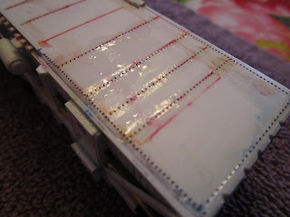
This side has 2.75" spacing (and 3.25" spacing on a
piece of decal for comparison) |
Even with my micrometer it was impossible to measure the exact rivet spacing on the drawing for all areas. Plus, the drawings showed some that were faded out because no draftsman could really draw them to scale and have them seen. I could have tried to extrapolate that information from the few pictures I had, but come on... it is a model. And I doubt that anyone at the judging can do a better job than me at figuring it out. Thus, I used the rivets I thought worked and looked best but I might had put a 5/8" diameter one where a 7/8" should go, and the spacing of 3.75" where 3.25" would be prototypical. So sue me! Complicating matters, I didn't have enough of the 3.25" spacing for the second side so the entire thing was done with 3.75" spacing.
You will never know the sides are different because they are so tiny!
The door areas were an interesting bit of cut and paste work. If you refer back to the prototype photo on my previous post you will see that what I did is a simplification of the prototype. Even with actual rivet decals, to try and cram them together into the prototype's pattern would result in a big clunky mess. In HO scale you have to draw the line somewhere, and this is where mine is. Admittedly, I am more concerned that once the car is primed and painted the rivet details will just disappear altogether. If that happens I will scream. Anyway, the picture to the right is a closeup of the car, and in real layout viewing distances it looks pretty good. It still looks naked without the grab irons though.

I am one of those "visual" people. For the handrails and grab irons, I needed to see exactly where they went in the prototype pictures to fully understand how to make them. Using pictures, and one of the photocopies of the plans that I had, I used a red pen to circle every place I had to install a handrail. I also measured them right off the plans (
which were photocopied to ensure 100% reproduction) and wrote down length and height of them as needed. I also do all my measurements in millimeters, which are convenient. The 0.015" diameter stainless steel wire I use is pretty resilient to accidental bumps, but nevertheless I first drilled all the holes on all for sides and then bent up and attached the wire.
The ends not only had grab irons but also the brake wheel, the cross-over platform for the brakemen to use between the cars, and some other interesting things. I will work on them next, reserving the roof for last because once the roof is done the car can't be turned over without risk of breaking off details. Then, the corner stirrups and final underside details will go be added and the car will enter the paint shop.
And now for some boring bookkeeping. The notes below are just so I can remember what I used where in the future:
▪ Sides #1 & #2 - upper / lower horizontal rows: 5/8" diameter; 2.75" spacing.
▪ Side #1 - Vertical rows: 5/8" diameter, 3.25" spacing.
▪ Side #1 - Vertical rows at ends: 5/8" diameter, alternate center spacing.
▪ Side #2 - Vertical rows: 5/8" diameter, 2.75" spacing.
▪ Side #2 - Vertical rows at ends: 5/8" diameter, alternate center spacing.
▪ Side Doors: 5/8" diameter, alternate center spacing.
▪ Ends - Horizontal rows: 5/8" diameter, 3.25" spacing.
▪ Roof - Perimeter: 5/8" diameter, 2.75" spacing.


 I am one of those "visual" people. For the handrails and grab irons, I needed to see exactly where they went in the prototype pictures to fully understand how to make them. Using pictures, and one of the photocopies of the plans that I had, I used a red pen to circle every place I had to install a handrail. I also measured them right off the plans (which were photocopied to ensure 100% reproduction) and wrote down length and height of them as needed. I also do all my measurements in millimeters, which are convenient. The 0.015" diameter stainless steel wire I use is pretty resilient to accidental bumps, but nevertheless I first drilled all the holes on all for sides and then bent up and attached the wire.
No comments:
Post a Comment