CP Executive train in Albany

CP Executive train in Albany

Monday, March 30, 2020

Scratchbuilding Flatcars - Part 2 (brake gear and grab irons)

I only used the hair dryer, not the stove's burner
It had been over a year since I had touched these two cars (except to move them around my workbench to clear space up) so when my caboose was nearing the end (see what I did there?) I was excited about jumping back into this project. I had left it off at a difficult spot: adding all of the brake lines. And I had unfortunately made a big mistake. I cut into the central support beams but then left the cars alone. When I came back to them a year later, they had developed a sway back. To fix that, I used a hair dresser and some weight to coax them into position. It worked, but I don't know how permanent it will be. I made need to adjust them again in the future.

The plans explain where to install the various pieces and piping but they assume that you can cut holes easily in the sides of the girders... once they are already installed on the underside of the car. The truth is that you can't. I tried twirling the tip of a hobby knife where I wanted the hole but it didn't work. That is why I had previously cut the girders in a couple of places. I then began working on adding the brake lines. I used brass 0.030" rod and some parts from a Details West (#DS-2012) metal brake gear set, as well as some Athearn styrene parts. I much preferred the styrene parts because MEK bonds to it. And then I had to repair all the girders I had channeled through.

Then, with the flatcars back to being flatcars, I began gluing on the stake pockets to the sides of the car. I formed them from two pieces of C-channel glued together and sliced into pieces. I had only done one of the four sides before quitting in 2019 so I had three sides to go. And try as I might, I couldn't get them to stick. It was as if my glue had turned to water. I tried over and over but throughout the morning they all fell off. The ones I had done last year were on rock solid. What changed? Then I realized I had kept metal cans of MEK and Lacquer Thinner on my workbench and had recently refilled my small MEK bottle. And, that bottle's nozzle wasn't working anymore either. Bingo Bango... I bet I was using lacquer thinner instead of MEK. After pouring out the bottle and substituting MEK, things began to stick again!

I then jumped back to the brake gear again. Piping was done using 0.030" brass rod and even finer 0.015 brass and styrene rods, sometimes bent to get around certain areas. Some parts had to be made with multiple smaller pieces on each side of a cross brace to give the appearance of one longer pieces running the length of the car. But, it came together in the end. I can really appreciate all the effort that certain modelers take when they make everything exactly as it should be. I did my best per the plans that I have see more complex cars before. I don't think it would be possible to approach this level of detail in N scale, that is for sure.

Once my stainless steel 0.015" wire arrived I began making things like grab irons and stirrup steps. For HO scale it probably would have been better to use even finer wire (0.008"?), but that just wasn't going to work for me. I ordered both stainless and brass wire but went with stainless because it is more durable. An online discussion about the best material for grab irons was pretty useful in my decision making. I didn't bother with a forming jig or anything like that; I just used my serrated-jaw pliers and put the wire in the serration notch every time. If I needed larger ones, I used a different notch. It worked pretty well, and the metal was surprisingly strong. I made lots of extra ones just in case.

Then, out came the #72 (0.025") drill bit and pin vise to drill all the holes. Despite being an extremely small bit, I only had it break once and that was because I got careless. The trick for me was to drill horizontally while supporting the bit with my index finger of the left hand while turning the pin vise with my right. The styrene was thin and cut easily. Worried about breaking lots of bits, I ordered a 6-pack of #72 bits from Micro-Mark. They cost $7.95, and $18.26 total with tax. That is over $3 a bit. Ebay has 10-packs of bits for less than $6 delivered. Are they just as good? Who knows, but they are much cheaper. In the future I will use the cheap ones until they prove unreliable. The grab irons were secured with superglue.

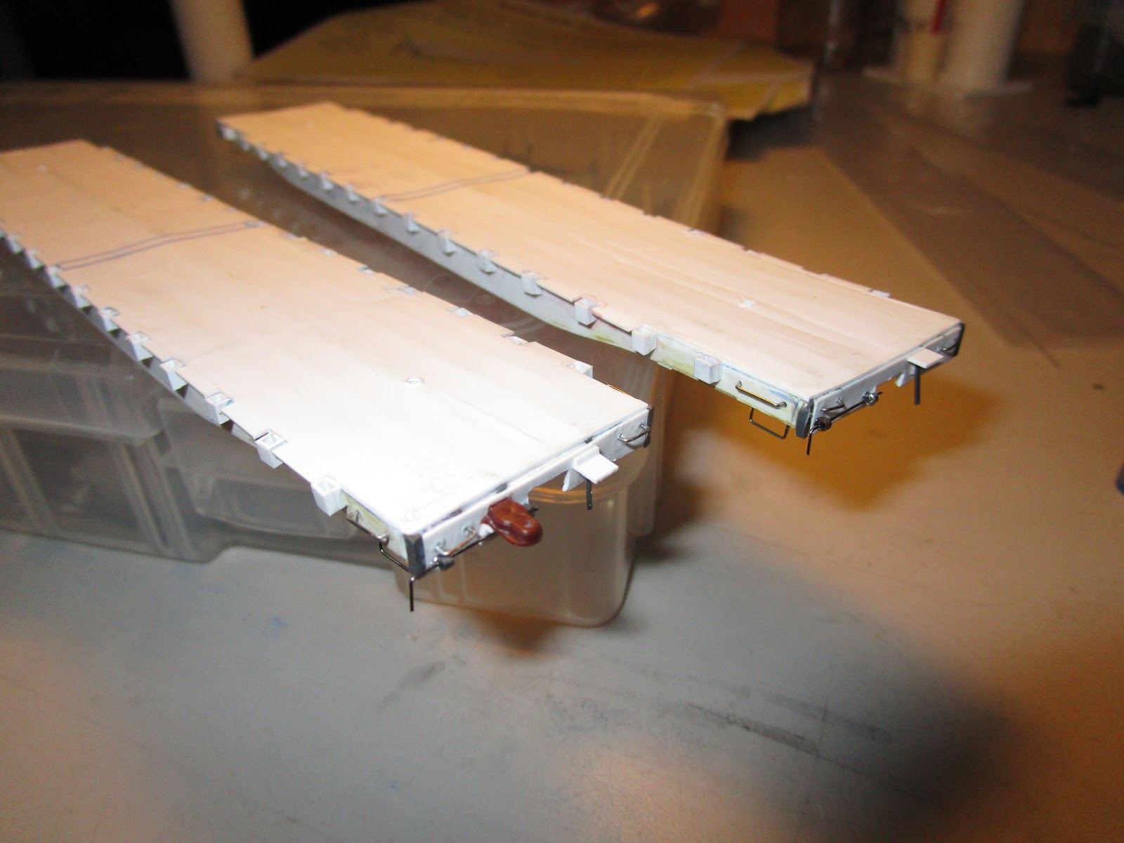
Next, I worked on the cut levers for the couplers. The prototype has a cut-lever design that works from only one side of each end of the car. The cut bar goes under the coupler and pulls the pin from the bottom. Since my cars will have Kadee couplers and draft gear boxes, and I am not exactly sure how much room the shanks will require to pivot, I modeled the cut levers up to the point where they enter the coupler shank area. I used more 0.015" stainless steel wire for the cut levers themselves, but for the wire support brackets I used cut down Athearn metal handrail stanchions (something I found to be really convenient.) I won't add the brake staff or brake wheel until the very end, because they will just get damaged otherwise.

Up next: the flatcars get a bubble bath, and then into the paint shop. After that, the wooden decking is installed and final details are added.

Saturday, March 28, 2020

Styrene Organizer - Version 2.0

Like most of you, I have suddenly found my nights and weekends free to do more modeling. As a result, my caboose finished up quickly and I am well on my way on my two scratchbuilt flatcars. Since I have been trying to avoid going out whenever possible, I have used Ebay to order everything from kit parts to styrene supplies to paint. It isn't always the most cost effective but it works. After recently receiving some tiny diameter brass, stainless steel, and styrene rods (used for making brake rigging and grab irons), my older styrene storage rack suddenly became overloaded. I had to build a bigger one (hopefully not like the Rich Young Fool described in Luke 12:16-21 of the Bible). 

My previous one was a compromise of sorts. It was built out of small dimensional lumber strips and dowels that I purchased at the store and it worked fine. It was also plenty strong, but bulky. However, because I didn't glue the wood dividers perfectly parallel some spaces were a little over size and some were undersize. For tiny strips of styrene it didn't matter, but for larger 1/4" square stock it was impossible to get everything in. And, because I had made the racks so narrow (5.5") I needed four of them to hold a sizable inventory. And they were just asking to be knocked over. I didn't want to go out for more wood and had no other material on hand except a huge amount of 0.040" styrene sheet. So, that is what I used. I was concerned that the thin 0.040" dividers might buckle and crack from the weight of the second shelf bearing on it but decided to try it anyway.

After cutting some pieces to the size of the base (12" x 15") and a lot more into strips that were 1/4" and 1/2" tall, I began the task of laying everything out and gluing it all together with MEK. How long did it take? Well, I managed to play three James Bond movies in the background during the project which I couldn't really watch but I could listen to (the car chase scenes are especially anti-climatic when you can't see what is going on). I took breaks every now and then to help clear my head because the measuring and cutting was tedious. Once it was all glued together, I went around and added trim pieces along the edges and in the gaps. I wasn't necessary but I was having fun and had nothing better to do.

Unlike the first design which used gravity to hold the shelves together, I added a wrap-around edge on the bottom shelf and this let the second shelf drop right in with plenty of clearance. Some more additional cross-strips along the top will prevent the styrene strips from bouncing out of the slots, but there is plenty of room to get a finger or pencil into them should I need to coax some pieces out. I did use some 0.060" I had on hand for some of the dividers, and a little bit of 1/4" square styrene rod to frame the edges and the inner divider for extra strength. All told, I used about $10 of styrene to build this and had I been willing to laminate 0.040" strips together more I could have probably gotten away with just using them, cutting the price in half.

I then noticed I was out of blue spray paint I wanted to use so I ordered some online. Since it was going to take several days to arrive, I got antsy and built a third rack that fits on top of the other two. I figure if I am in the mood to build them I might as well do it now instead of sometime in the future when I actually need them. If they sit half empty, who cares?

Then, everything received a bath in soapy water and when they all were dry I painted them with the same Rustoleum Satin Ink Blue paint as my old racks. I really like the blue color, and the white styrene really pops out visually. For fun, I also took some scrap cedar wood and 1"x4" stock and threw together a quick sheet styrene holder. It is essentially a large napkin holder. Excessive size styrene sheets are still on another shelf, but once they are cut down smaller they can migrate here. I still need to figure out something for my metal wire, but that shouldn't be too tough. I might glue small lengths of PVC pipe underneath the racks to serve as legs and holders, or perhaps I will build another shelf.

Thursday, March 26, 2020

Roster Review: D&H low-nose RS11s in 1984

I have previously documented the D&H's high-nose RS11 engines that were on the roster in 1984, but hadn't researched the low-nose engines until recently.

As was mentioned earlier, the low nose engines (#5000-5005) were originally built by Alco for the New York Central (in early 1960) and were later purchased by the D&H. The low nose engines (#5006-5011) were ordered directly by the D&H (in May of 1961) who specified low noses. Whatever was stored in the high-nose wasn't needed by the D&H, or perhaps Alco figured out another location on the engine to hold those internals. The advantages of greater sight lines for the engine crew had resulted in nearly all new engine builds by the major locomotive manufacturers having low noses, a trend that continues to this day. The low nose units actually weighed a little bit more than the high-nose engines, likely because the D&H ordered them with additional ballast for adhesion.

All of the engines were originally delivered in the lightning stripe scheme with the words "Delaware & Hudson" in small letters along the upper sides of the hoods and road numbers in the same size font below them.

#5006 (May 17, 1881)
In 1984, engine #5006 still had the lightning stripe scheme with the lettering "Delaware & Hudson" in small font centered on the hood, and no road numbers on the side. Engine #5008 also still had the lightning stripe scheme and it didn't appear to to have been patch painted with the larger numbers, but the sides of the engine are so grubby that it is impossible to determine how much of the original "Delaware & Hudson" lettering or small numbers remained. Meanwhile, engine #5009 had the lightning stripe scheme but with the distinctive the large numbers on the side of the hood and the lettering "Delaware & Hudson" in smaller font below it.

#5007 (August 12, 1985)
#5007 - this engine received the plain "Altschul blue" dip scheme in 1977, which it kept through 1984. In my opinion, considering it never received the yellow sills or chevron stripes on the ends it it one of the most simple, and perhaps unattractive, of all of the engines on the D&H. The shields on the front of the hood and on the sides of the cab also weathered to a near-white appearance which did nothing to help things. However, it is very easy to pick out this engine in pictures of the D&H trains. If there was an engine to practice skills such as custom-painting (and weathering), this surely would be the one to start off with!

(1985)
#5010 & #5011- were later repainted in the more involved blue scheme with yellow chevrons and yellow sill stripe sometime after August 1979, which it kept through 1984.

By all accounts, that means the six low nose engines above were displaying at least four different paint schemes in 1984! Most of these engines survived until the end of the Guilford period of ownership of the D&H, but several were then scrapped. Engine #5010 still operates in western New York on the Buffalo Southern Railroad, and I read online that #5011 went to a museum in Kentucky. Beyond that, I am unaware if any of the other low nose RS11 locomotives survive.

#5004 (October 1982)
One other engine that I am including in this post even though it probably doesn't belong here is #5004. In 1973, the unit was involved in an accident and during the rebuilding and repair work by the D&H its nose hood was replaced with a cut-down tall hood. This resulted in a unique engine as the corners of the now short hood had the angled cutaways where the sand boxes access hatches were. The visible sandbox access hatches make identifying this engine easy. In 1984, the engine was still in the lightning stripe scheme with large numbers on the sides and the words "Delaware and Hudson" below them... likely ghosting through from the earlier paint scheme. 

Atlas offers a model of the #5004 but it isn't clear from their website if it has the cut-down short hood with sandbox notches or the original high nose. Meanwhile, the Walthers site lists the engine but has a picture of the high nose 5003, so I can't rely on them either. Who knows?

Tuesday, March 24, 2020

Then and Now: Bridge Street overpass (North Albany Yard)

(April 1975)
The Delaware & Hudson's North Albany yard was right across the street from what is now Huck Finn's Warehouse, which was originally an extension of Montgomery Wards. Right across the street (literally) was Bridge Street, which cut across the yard on a small bridge that was supported by stone piers. This street was very narrow, though I think it was actually two lanes. I don't know how long it lasted as a thoroughfare but at least by the 1970s the bridge itself had been removed. Looking at the picture at right, it is hard to imagine how much clearance there was between the underside of the bridge and the railroad tracks beneath. The perspective from the camera view is likely misleading.

By 1984 at least one of the bridge piers had been removed, as had the road structure completely. But, at least one of the piers was left standing as a testament to the road that had once been there. Since one of the sections of my layout sections (the staging yard) is supposed to represent the North Albany yard I think it would be an interesting detail to build a bridge pier. You can also see in the picture the status of the railroad yard itself to the right... not much going on except that removing the tracks (thank you Guilford). But, all of that should make for an interesting and unusual scenic model. I can't wait to get started on it.

March 2020
When I set out in 2010 to photograph and document what was left of the area, I had notations on some old maps of Bridge Street. But, I just couldn't see the road anymore (it was truncated on the east side of the tracks a bit) and there obviously was no bridge. However, it was July and there was a tremendous amount of brush. Over the years we have been to Huck Finns to buy furniture, to watch nearby fireworks, and in the winter my commuter bus sometimes goes by. That is when I saw the abandoned bridge piers. It is really tough to make out but in that pile of brush on the right is a pier.

And, here is another pier right outside the entrance to Huck Finns. I always assumed that it was part of a stone retaining wall but that it not the case. Instead, I suspect that it is also more remnants of the bridge as well. This is just another example of why I find railroad archaeology so fascinating.

Tuesday, March 17, 2020

Scratchbuilding a Caboose - Part 8 (end railings and weathering)

The end railings were fabricated from some K&S 1/32 brass rod (#8160) that seemed to be the right scale. The prototype hand railings had a somewhat distinctive flattened portion where they made ninety-degree curves at the corners but I just left them round. In this scale I didn't think they would be noticeable. I built up a soldering fixture on a scrap piece of wood using some dimensions I took from the actual car. Had every railing hole been perfectly drilled and equal on each end I would have only had to make one. But, I am not perfect and one hole was slightly off so I drew it up twice. T cut the brass rod with rail nippers which left one end nice and flat, which I butted up to the railing.

I then used some paste flux and solder and soldered them up. I built up a little fillet in the joints for strength, and I was surprised at how strong they were. When I later trimmed the bottom pieces to length I was afraid the vibration from the cutters would break the joint but it didn't. These aren't the first handrails I have ever made... I made a set of custom ones for a G-scale 44-tonner and those were silver soldered together for extra strength. Had these broken, I would have used silver solder to repair them. But, my silver solder is pretty thick in diameter so I avoid using it unless absolutely necessary. The railings were then glued in place, with a little bit extra of thin super glue at the bottom to form a fillet... which in this case is prototypical!

The brass brakewheel casting I had purchased from Precision Scale Company strong. I cut it off the sprue with dykes (thank goodness I didn't try my rail nippers) and then the belt sander and files removed the excess sprue. I soldered it to more 1/32" brass rod, and bent the rod end in at the bottom to meet up with the end of the "brake line" I had fabricated. A small styrene shim under the brakewheel represents the support bracket. The castings didn't come with a ratchet wheel for the bottom of the shaft and I didn't want to make one, so it doesn't have one. Mud splashers were 0.020" styrene that I superglued on. To say that they came together quickly and easily is an understatement, and I am over the moon that it went so well.

The first coat of initial weathering was a acrylic paint wash made from brown craft paint and water. This went on the underside and it was applied somewhat heavily as it was a very thin wash. I tried to prevent large water spots and collections of paint, which would look odd. Then, I dry brushed different shades of black and brown paint to blend in the wash. The brake shoes were given a lighter brown color to represent rust, as was the brake lines and the wheels. The journals were dabbed with gloss black to represent the oily packing inside which leaked out. This picture makes it look pretty garish, but in real life it is much more subdued.

Because I am more familiar with the properties and drying qualities of oil paint washes, I used them to weather the caboose body and the roof. For the body, I mostly stuck with brown and kept it light to represent a well kept up caboose. It settled in the cracks around the windows and boards but otherwise just served to lighten the red. A very light hand with a black wash brought out the boards a bit. The roof was given a brown/black wash to represent dirt blown up and coal smoke. I would have loved to add crushed fine coal to represent cinders but I can't think of a way to attach it without the adhesive showing. The smoke jack was dry brushed brown.

For the end platform decking I originally planned to use more of the Evergreen scribed car siding but the board width was just a bit too narrow to represent the prototype. Naturally, nothing in my stock of strips matched the width I wanted (0.100") and I didn't want to cut them from a larger sheet because thin strips like this tend to curl which would look terrible. So, I ordered some Evergreen 0.100" wide x 0.040 thick strips (#145) and used them. I built up two thin decks, one for each end, and then used sandpaper and other tools to roughen up the boards and make them look worn. Nothing too serious though. They were then painted black and glued in place. A builder's plaque was also added.

An O scale caboose straddling HO scale tracks.
The only thing left to do is install glazing, which will be cut from some thin microscope glass slide covers that I purchased online. I ordered them cheaply from China so they will take another month or so to get here. Until then, I cannot officially call it "done." But it is. It sure looks short and stumpy, and a bit ugly perhaps. But, it is all mine and likely one of the only models existing of D&H caboose #10. And I am very proud of it. Now I have to wait until October for the NMRA Northeaster Region "Mill City" convention to enter my car for merit judging. The paperwork is finished and ready to go. Since I don't plan to actually attend the convention, I will be driving the caboose up early in the morning and then waiting around until it has been reviewed and judged. Then, I will come home.

My next projects include two flat cars which I haven't touched since March 2019, over a year ago. I stopped all progress on them when I diverted my scarce time to my 7.25" gauge diesel locomotive and bulkhead flatcar riding car projects. But, with my caboose safely stored in a special travel fixture I built to prevent damage in transit I can shift to my next projects. With any luck, I might have those flatcars available for judging in October too. And, I am already collecting research for my next two cars. The fun never stops!

Thursday, March 12, 2020

Colonie Shop log books for May 1984

It is funny how much research material is out there if you just know where to look. Or, in my case, happen to stumble upon it.

I used to participate in a D&H Yahoo group and in 2011 I came across a thread that interested me. Mike Bischak, who went by the handle of "Breezy," had acquired many of the D&H's Colonie Shops log books which contained information about the engines that were in for service. We talked then and he offered to copy some pages for me, but I didn't know exactly what or when I was modeling so I thanked him and filed away our emails. This week on an impulse I emailed him again and unbelievably within hours he had sent me several pages scanned from the log book. With his generous permission, I am putting two of the scanned pages on the blog because I think that they are pretty fascinating. You can see that on May 26 (page 39) it looks like sixteen engines are listed as requiring something or another. Another three engines are listed on the left as needing supplies. I don't think the shop could hold nineteen engines so most must have been outside.

As it turns out, I might have outsmarted myself. I know I wanted to model May 1984 and picked my birthday, May 28. But, in 1984 that was the Monday when Memorial Day was celebrated. I don't know if the Colonie Shops were open that day. There is no page 40 in the log book (it is there but is blank) so page 41 is either May 27 or May 29 (page 41). It cannot be determined based on later pages. But, it too was a pretty busy day for the boys in Colonie. Most of the eighteen engines are the same as from the days before. One two new ones are added. The list on the left is more extensive, but I don't know what that means.

While I have said that just about any diesel engine from 1984 could have found itself on the Colonie Main, here is a definitive list of those that actually were there. Running? Maybe, maybe not, depending on what they were in for. Only one model engine (#7323) that I own to date is listed here, but that was for an "engine change" so likely it shouldn't be actually running on my layout. Shhh... don't tell anyone!

I owe Mike a big "Thank You" for somehow acquiring this excellent resource and making it available. 

Tuesday, March 10, 2020

Scratchbuilding a Caboose - Part 7 (end steps and black chassis)

I have been going back and forth as to how to make the steps for a while. The prototype ones are small and almost fragile looking, which for a model would translate into fabrications that are difficult to make and easily broken. Not a great combination for a model, even such as this one that probably will only sit on a display shelf. Many caboose building articles I have seen in print and online call for using castings, which is great if you can find what you want. One I read recently even showed etched brass HO scale caboose steps pretty much exactly like the ones I needed, but this caboose is O scale. I didn't easily see something suitable in an online search. And, I didn't want to lose merit points. So that meant scratchbuilding.

I had two options for materials: brass or styrene. As much as I love the later, I had no way to bend the thin stock to the zigzag stringer shape required without it breaking and cutting L-angles into lots of little pieces and trying to piece them together into a zigzag seemed tedious. That left brass stock. It could be bent easily and soldered together, hopefully resulting in a strong bond. I took a full size scale print to the hobby shop and picked up a couple of sizes of brass stock: #815020 (1/64" x 1/16") for the supports and #815021 (1/64" x 3/32") for the steps. Getting it out of the package without kinking it is best accomplished by slicing along the bars with an X-acto knife.

I measured up some dimensions (in millimeters, as is my usual practice) and considered building a wood former. But, I was only making four stringers and didn't want to go crazy. Instead, I laid out some critical dimensions on a piece of thick styrene (itself fabricated from three layers of my 0.040" stock I have all over the place) and used various colored Sharpie thin point markers to indicate various bend spots. Hint: a multicolor pack of the markers is wonderful and the ability to use different colors on various materials without it smearing is really helpful. Once this was done, it was time to stop stalling and start bending brass.

I glued various pieces of styrene to the former as I went about my bends. I never used the styrene as a bending point because it would never have given me the sharp corners that I wanted. Instead, after laying the brass strip in the jig and marking where to bend I pulled it out and bent it with pliers. I wish I had paid more attention to those guys at train shows who sell various pointed pliers, because my smooth jaw round needlenose pliers weren't the best tool. Next year at Springfield, I am stocking up! But, they managed. After every bend, I dropped the stringer into the jig to check for the fit. Then, I glued another couple of pieces of styrene onto the jig and let it set and then made the next few bends.

As I got near the bottom I noticed that some of the bars didn't always want to lay flat. Rather than just using fingers to adjust it (and possibly messing up a bend somewhere else that I didn't want to change) I stuck it all back in the pliers and fiddled with it. It was very springy which was both good and bad. But, in less than an hour I had managed to get all four pieces bent into the proper shape (without myself getting bent out of shape) and all relatively equal to one another. Then the excess was cut off. Considering I was essentially making this up as I went along, I was surprised how well it worked. Of course, the soldering step which is next would determine whether the method was viable or not.

To prepare the brass zigzag supports for soldering the step boards onto, I needed to find a way to securely hold them parallel to one another, with the proper spacing equidistant between them, and also conveniently enough to get access to solder them. Nothing fancy was required, and some short pieces of left over wood were quickly marked with some dimensions for spacing and centerlines and then glued together. I considered using screws from the top with the screw heads overhanging the brass stock to hold them to the wood but worried they might kink the thin brass if the screws didn't go in perfectly flat. Tape didn't seem the right answer either. Looking around, I saw a bottle of white glue and ran a few beads over the tops of the pieces after aligning them how I wanted them. Once soldered, soaking in water will hopefully release them.

In addition to the zigzag stringer there are two parts to the steps: the horizontal tread boards and the vertical risers boards. Since it isn't easy to solder both at the same time (the risers will fall off because they are vertical) I first worked on the treads. They were cut from brass and then the corners were rounded with a file to match the prototype. Tedious, but there were only eight to do. Soldering was pretty painless though I had to frequently adjust the stringers to make sure things lined up. If they had bent identically to one another then it would have been a breeze. As it is, though, I think that they came out fine. I didn't solder the bottom board because it is longer than the other treads and had I done so I wouldn't have been able to fit the steps over the platform... it would have bound.

The pieces that go in the back were a separate matter. I tried long and hard to think of a way I could solder them on but I just don't have clamps or pliers or any other way to keep what I already did together without the heat from the iron working it loose. I tried JB Weld epoxy but the joint areas were so small that it didn't work and the pieces easily came off. After cleaning them up again, I used really thin super glue to attach them. It filled in the voids and made a bit of a fillet on the back. A couple broke off during installation and they were attached with super glue gel, which worked a lot better. I hope they hold long enough for the caboose to survive judging. After that, I don't care! 

The end platforms were drilled with a #60 bit for the railings which I still need to build. That hole may be too small, but it will be a useful starter hole.

Then, the chassis was washed in soap and water and left to dry for a couple of days. As for painting it, I have no pictures of how D&H bobber cabooses were painted 150 years ago. It currently has a gray frame with black axle boxes, black metal stair straps, red tread boards, and gray riser boards. I think it looks pretty gaudy, and my chances of painting it cleanly are pretty low. As the Rolling Stones would say, "I want to paint it black" and instead went with the all black underside below the body, which I think looks better and matches other D&H cabooses.

I used Testors flat black from a spray can to paint the chassis with several light coats. There were lots of nooks and crannies that the spray paint wasn't getting to, so I switched to a brush and a bottle of the same paint and did some touch up work. The brass step assemblies were also sprayed black and then they were glued onto the chassis. Looking at it all, the flat black is too flat for my liking but once it is lightly weathered the details may come out more. In the picture I had just attached the lower steps made from brass Special Shapes Co. #85026 (1/32" x 1/8") stock. They still need to be painted, and some areas need black touch up paint.

Right now, the steps are a big jump for me skill wise. I have never built something like this in brass before and wish I could have figured out a clamping system so that all of the pieces could have been soldered together. The superglue works, but the bond much weaker. Not all of the steps are perfectly level, the same size, or profiled in the corners the same way either. It looks like an old, beat up bobber caboose. That wasn't the look I was going for when I started, but it is the direction I am now going. I wish I could build it better but I can't. This is my first scratchbuilt caboose and I am going to have to live with it, warts and all. I am still very proud of what I have done. Perfection can come on later models as I gain more experience. And, at the end of the day, I can't lose sight of my goal: 87.5 out of 125 possible merit judging points. That is only 70%. 

Only a few more things are left to do. I need to add the decking on the top of the caboose steps. I also need to fabricate the end railings and brake wheel. Then, some weathering and installing the window glazing will finish the model.

Friday, March 6, 2020

Lionel latch couplers on a 44-tonner engine

Admittedly this project is about as far as you can go from modeling the Delaware and Hudson but it is train related. And it is my blog. So...

About a year ago I picked up some United States Toy Train Company models which were decorated in the Arcade and Attica Railroad's colors. I always wanted an engine to pull them but most Lionel and MTH steam engines are too realistic to look appropriate with the cars. And, I love 44-tonners and Lionel made one that really isn't a 44-tonner anyway (it is more like an 80-tonner in size). That is fine by me, as the A&A owns one of them too. But, the couplers on the Lionel model aren't the toy "latch" style that is on the cars. They don't look realistic or work all that well to be honest, but that is what the cars came with.

It wouldn't have been too difficult to convert one of the cars to Lionel knuckle but I didn't want to go down that road because the cars are extremely rare. Lionel 44-tonners are a dime a dozen engine. So, switching a coupler on it was the path I was going to take. But, I am not a Lionel guy and really didn't know what I was doing. I acquired a used #627 Northern Pacific engine from a good friend and during a slow weekend I decided to start on the project. The engine comes with one powered truck, and a light on the opposite end of the engine. Sadly, the coupler that I had to change was the one on the same side as the light which means the engine won't have a headlight facing forward when running (unless I somehow figure out how to reroute and install the lightbulb... unlikely).

The unpowered truck has a lot of plastic underneath so I test glued some styrene to it with MEK. That is what that little piece of thin white styrene is that is right near the center rail collector rollers. After confirming it did bond strongly, I built up a pad with 1/8" styrene and MEK. Once it cured, I drilled through it and used a 6-32 screw and a nut to confirm the correct height. I had to bend the coupler shank a bit to get the correct height and the thin metal is fragile so care was necessary. After checking the swing, I removed the coupler and painted the styrene black. Then the coupler was reinstalled and a tiny dab of threadlocker was added to the nut to prevent it from working loose.

Success!
One thing I noticed when coupling the engine and the coach together for the picture was how difficult it was to get the couplers to engage. Considering the basic premises is a hook that extends from the bottom of the coupler that is supposed to push past (or perhaps knock up) a horizontal bar that then drops down after the hook has gone through, preventing the hook from pulling loose. What a stupid system! It not only is extremely finicky it trying to get them to engage together (forget backing into a string of cars with a gentle click and then pulling away with them) but it doesn't have to be that difficult. Hook and loop cars are also unrealistic but work much better. Thankfully, Lionel finally developed into more realistic knuckle couplers.

I still need to disassemble the frame and mechanism and clean and degrease it for painting, but that is a project for another weekend.

Monday, March 2, 2020

Rebuilding North Albany Yard (Staging yard)

Once I had my MMR Civil certificate in hand, I could finally begin the process of rebuilding the fourth section of my layout. Certain things had to go: the turntable, the storage tracks, and the switchback lead. Some things were going to stay, such as three of the yard tracks. In the process, I decided to flip the last switch around and create a fourth yard track. They aren't very long, but this isn't really supposed to serve as an active staging yard. If anything, it is just a place to keep train cars on the layout so I don't have to walk across the basement to dig them out of storage boxes.

I first began by cutting all of the unnecessary wires underneath and disassembling everything. I had anticipated this day would come so I didn't secure them very well and they came apart easily. I made sure to keep all of the wiring as I seem to run out of it just when the stores close. I discovered that my lightly-glued down tracks were actually securely glued down and took some effort to remove. The cork roadbed which had been secured with wood glue was a real bear to take out and I had to use a utility knife to slice it into small pieces and then gouge it away with a putty knife and chisel. Elmers glue probably would have been easier.

Beads indicate where to add feeder wires
The yard itself was laid on craft foam sheets that I purchased at a hobby store. Originally I was pleased with them because they laid relatively flat (unlike sheet cork) and they were cheap. But, over time they bubbled and created undulations in the tracks. This made the yard look somewhat realistic so I didn't mind it at first, but in relaying the track I had trouble with the track joints because securing the track to the foam wasn't good enough. So, I shimmed the foam bubble areas with styrene that I spiked down to the plywood and then glued the track to the shims. Those areas are now secure. In the future, I will switch back to cork roadbed or sheet or just lay the track on the plywood.

When I originally wired the section I set it up so each of the yard tracks could be turned on and off with a switch (an Atlas selector). I didn't really care about that feature anymore, so I wired all of the yard tracks together to the DCC bus line. In the future if I want to add it back in it is easy to cut the wires below as they are neatly arranged. However, in a concession to my partial laziness I did also glue down a small separate pieces flex track next to the yard. It isn't connected by rail to the rest of the layout nor is it wired up. It sort of looks like a partially ripped up yard track. But, I can physically put a second engine there when I want to have two on the layout and it won't run off on my or have its sound effects drone on.

After everything was wired up, I painted the track with the usual Rustoleum camoflauge paint and then scraped the railheads clean. The ground throws were connected with the wire-in-tube method as I did elsewhere.